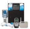
Hayward Pro Logic Model: PL-PS-4 PL-PS-8 PL-PS-16 PL-PS-16V Operation - Page 8
Pool/Spa Valves, Heaters, System Off, Service, Diagnostic Menu - controls replacement parts
 |
View all Hayward Pro Logic manuals
Add to My Manuals
Save this manual to your list of manuals |
Page 8 highlights
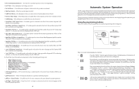
VSP Relay: This selection is used to configure a Lights/Aux output to supply power and control a Hayward Variable Speed pump (VSP). Pool/Spa Valves Pool-only or Spa-only systems: The POOL/SPA/SPILLOVER button has no function. Standard Pool and Spa systems without spa spillover: In pool-only mode ("POOL" LED illuminated), press the "POOL/SPA/SPILLOVER" button to switch to spa-only operation ("SPA" LED illuminated). Pressing the "POOL/SPA/SPILLOVER" button again will switch back to pool-only. Note that the filter pump will turn off while the pool/spa valves are turning. Standard Pool and Spa systems with spa spillover: When currently in the pool-only mode ("POOL" LED illuminated), press the "POOL/SPA/SPILLOVER" button to switch to spa-only operation ("SPA" LED illuminated). Press the button again to switch to spa spillover operation ("SPILLOVER" LED illuminated). Pressing the "POOL/SPA/SPILLOVER" button again will switch back to pool-only mode. Note that the filter pump will turn off while the pool/spa valves are turning. Dual Equipment Pool and Spa systems without spa spillover: The POOL/SPA/SPILLOVER button has no function. The "POOL" LED will always be illuminated. Dual Equipment Pool and Spa systems with spa spillover: When currently in the separate Pool and Spa loops mode ("POOL" LED illuminated) and the Spa Filter is off, press the POOL/SPA/SPILLOVER button to switch to spa spillover operation ("SPILLOVER" LED illuminated). Press the POOL/SPA/SPILLOVER button again to return to the separate Pool and Spa loops mode of operation. Note that the Pool Filter pump will shut off while the pool/spa return valve is turning. The system will automatically switch out of spillover whenever the spa filter pump is turned on. NOTE: For Dual Equipment Pool and Spa systems, there is no Spa Only mode. Heaters This description applies to Heater1 and to Heater2, if programmed (note that the function of the Valve4 button changes to Heater2 when Heater2 is enabled). Pressing the "HEATER" button causes the Pro Logic to switch the heater control output between a "forced off" state and a normal, automatic thermostatic control operating state. System Off Each remote display/keypad has a red "SYSTEM OFF" button on the upper left corner of the keypad. Pressing this button will turn all outputs off and they will remain off, regardless of any programmed control logic, until either the "SYSTEM OFF" button (on any remote display/keypad) is pressed again or the "SERVICE" button is pressed on the display/keypad at the main unit. The red "SYSTEM OFF" LED will illuminate to indicate that all outputs and being forced off. ! WARNING: pressing the "SYSTEM OFF" button overrides any programmed freeze protection and may cause damage to your system in freezing conditions. Service The main unit keypad has a "SERVICE" key. This button is used primarily during servicing of the pool equipment. If you want to completely disable the automatic operation and operate the system manually, you can put the system into Service or Service-Timed mode by pressing the "SERVICE" button. Pressing the "SERVICE" button once will switch the system into service mode which means that all automatic functions are disabled, and the remote display/keypads are disabled (except for manual turn off for emergencies). The red "SERVICE" LED will be illuminated and the Pro Logic will remain in this mode of operation until manually taken out of service mode. Pressing the "SERVICE" button again will cause the Pro Logic to switch to service-timed mode which is very similar to service mode, except that the Pro Logic will automatically return to normal operation after 3 hours. During service timed operation, the "SERVICE" LED will flash and the time remaining will be displayed on the remote display keypad(s). Pressing the "SERVICE" button again, will return the Pro Logic to normal (automatic) operation. See Troubleshooting/Diagnostic Information for more information about the service modes. 5 • pH Timeout - Check Feeder -- If the unit has been dispensing pH for more than the selected timeout without reaching the desired level. Check the chemical supply and the feeder. If both are OK, the timeout may need to be increased. Press the "+" button to reset the alarm and resume dispensing. • pH Calibration Error -- When using the pH Calibration Wizard and the entered test result was different from the measured pH level by ± 1.0 or more. The pH probe may need to be cleaned or replaced. • ORP Probe Error -- If the CSM indicates that there is a problem with the ORP probe. • ORP Low - Check Chlor -- If an ORP level of 350mV or less is detected. Check the chlorinator for proper operation. • ORP High - Check Chlor -- If an ORP level of 950mV or higher is detected. Check the chlorinator for proper operation. • ORP High - Chlor Off -- If an ORP level of 950mV or higher is detected and the chlorine feed mode is ORP Auto Sensing, the chlorinator has been turned off. Check the chlorinator for proper operation. • ORP Timeout -Chlor Off -- If the unit has been chlorinating for more than the selected sanitizer timeout without reaching the desired level, the chlorinator has been turned off. Press the "+" button to reset the alarm and resume chlorination. • Ambient Sensor-- If the Pro Logic internal temperature sensor is either an open or short circuit. For helpful troubleshooting information on any of these issues, go to the Diagnostic Menu and then scroll through the various items until you see the cause for the "CHECK SYSTEM" LED being illuminated. Diagnostic Menu To enter the Diagnostic Menu, press the "Menu" button repeatedly until the display shows "Diagnostic Menu". At this point, you can use either the "" buttons to scroll through the various menu items which are described below: +S2e3t.4D5ay an+d6T.i7m5eA W84e°dFnesd3ay2010P:3P7MP Press to switch chlorinator operation to opposite polarity (15 second delay) Move to previous/next menu item +/- 23.45V is the voltage applied to the chlorinator cell +/-6.75A is the current (amps) through the cell 84ºF is the water temperature at the cell 3200PPM is the "instant" salt level at this time This display will be shown only if the chlorinator is enabled. For the chlorinator to be operating, several other things must be happening: the filter pump must be running, the flow switch must be detecting flow, the chlorinator setting must be set greater than 0%, the water temperature at the cell must be between 50ºF and 140ºF, and the salt level must be within the operating range. If any of these conditions are not met, the chlorinator diagnostic display will tell you the reason. It's possible to have more than one reason, in which case after you rectify what was displayed the first time, a second display will appear. If the current (amps) display is 0.00A, then the chlorinator is operating normally but is in the off part of its normal operating cycle. Simply press either the "+" or "-" key to start a new cycle. The Pro Logic periodically reverses the polarity of the voltage applied to the cell in order to automatically clean off any calcium deposits. It is important that you check the chlorinator operation in both polarities. To do this, press either the "+" or "-" buttons and the chlorinator will turn off, wait for 15 seconds and then turn on in the opposite polarity. 42
-
 1
1 -
2
-
 3
3 -
 4
4 -
 5
5 -
 6
6 -
 7
7 -
 8
8 -
 9
9 -
 10
10 -
 11
11 -
 12
12 -
 13
13 -
14
-
15
-
16
-
17
-
18
-
19
-
20
-
21
-
22
-
23
-
24
-
25
-
26
 |
 |
