Hayward Super Pump® VS Super Pump® VS Manual - Page 2

Super Pump Variable Speed Pump, Table of Contents

Page 2 highlights

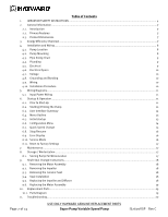
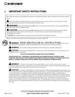
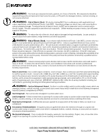
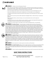
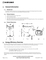
Table of Contents 1. IMPORTANT SAFETY INSTRUCTIONS ...4 2. General Information ...7 2.1. Introduction 7 2.2. Primary Features 7 2.3. Product Dimensions 7 3. Energy Efficiency Overview ...7 4. Installation and Wiring ...8 4.1. Pump Location 8 4.2. Pump Mounting 8 4.3. Pipe Sizing Chart 9 4.4. Plumbing 9 4.5. Electrical 9 4.6. Electrical Specs 10 4.7. Voltage 10 4.8. Grounding and Bonding 10 4.9. Wiring 10 4.10. Installation Procedure 10 5. Wiring Diagrams...11 5.1. Input Power Wiring 11 6. Startup & Operation ...11 6.1. Prior to Start-Up 11 6.2. Starting/Priming the Pump 11 6.3. User Interface Summary 12 6.4. Menu Outline 13 6.5. Initial startup 13 6.6. Configuration Menu 14 6.7. Quick Speed Change 15 6.8. Stop/Resume 16 6.9. Error Display 16 6.10. Service Mode 16 6.11. Reset to Factory Settings 17 7. Maintenance...17 8. Storage / Winterization ...17 8.1. Storing Pump For Winterization 17 9. Shaft Seal Change Instructions ...18 9.1. Removing the Motor Assembly 18 9.2. Removing the Impeller 18 9.3. Removing the Ceramic Seat 18 9.4. Seal Installation 18 9.5. Replacing the Impeller and Diffuser 18 9.6. Replacing the Motor Assembly 19 10. Replacement Parts ...19 10.1. Parts Diagram 19 11. Troubleshooting...20 Page 2 of 24 USE ONLY HAYWARD GENUINE REPLACEMENT PARTS Super Pump Variable Speed Pump IS2600VSP Rev C

  • 1
  • 2
  • 3
  • 4
  • 5
  • 6
  • 7
  • 8
  • 9
  • 10
  • 11
  • 12
  • 13
  • 14
  • 15
  • 16
  • 17
  • 18
  • 19
  • 20
  • 21
  • 22
  • 23
  • 24

USE ONLY HAYWARD GENUINE REPLACEMENT PARTS
Page 2 of 24
Super Pump Variable Speed Pump
IS2600VSP
Rev C
Table of Contents
1.
IMPORTANT SAFETY INSTRUCTIONS
..............................................................................................................
4
2.
General Information
.....................................................................................................................................
7
2.1.
Introduction
7
2.2.
Primary Features
7
2.3.
Product Dimensions
7
3.
Energy Efficiency Overview
...........................................................................................................................
7
4.
Installation and Wiring
................................................................................................................................
8
4.1.
Pump Location
8
4.2.
Pump Mounting
8
4.3.
Pipe Sizing Chart
9
4.4.
Plumbing
9
4.5.
Electrical
9
4.6.
Electrical Specs
10
4.7.
Voltage
10
4.8.
Grounding and Bonding
10
4.9.
Wiring
10
4.10.
Installation Procedure
10
5.
Wiring Diagrams
.........................................................................................................................................
11
5.1.
Input Power Wiring
11
6.
Startup & Operation
...................................................................................................................................
11
6.1.
Prior to Start-Up
11
6.2.
Starting/Priming the Pump
11
6.3.
User Interface Summary
12
6.4.
Menu Outline
13
6.5.
Initial startup
13
6.6.
Configuration Menu
14
6.7.
Quick Speed Change
15
6.8.
Stop/Resume
16
6.9.
Error Display
16
6.10.
Service Mode
16
6.11.
Reset to Factory Settings
17
7.
Maintenance
..............................................................................................................................................
17
8.
Storage / Winterization
..............................................................................................................................
17
8.1.
Storing Pump For Winterization
17
9.
Shaft Seal Change Instructions
...................................................................................................................
18
9.1.
Removing the Motor Assembly
18
9.2.
Removing the Impeller
18
9.3.
Removing the Ceramic Seat
18
9.4.
Seal Installation
18
9.5.
Replacing the Impeller and Diffuser
18
9.6.
Replacing the Motor Assembly
19
10.
Replacement Parts
.....................................................................................................................................
19
10.1.
Parts Diagram
19
11.
Troubleshooting
........................................................................................................................................
20