Hayward TriStar® VS Owners Manual - Page 6
TriStar Variable Speed Pump Control, USE ONLY HAYWARD GENUINE REPLACEMENT PARTS, Installation Notes
 |
View all Hayward TriStar® VS manuals
Add to My Manuals
Save this manual to your list of manuals |
Page 6 highlights
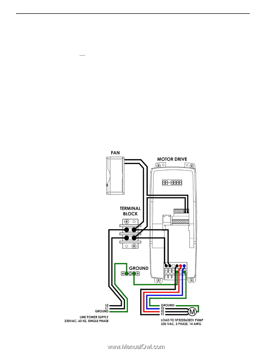
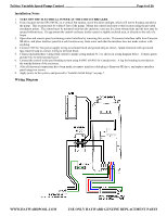
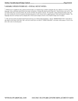
TriStar Variable Speed Pump Control ____ Page 6 of 16 Installation Notes 1. TURN OFF THE ELECTRICAL POWER AT THE CIRCUIT BREAKER. 2. Find a location for the SP3220VSC on a vertical flat surface, out of the direct sunlight, which will not be flooded, and above the pump. This location must be within 8 feet of the pump. Mount the control enclosure to this location using the provided attachment points. The control must be mounted such that the enclosure vents are free from obstructions and the door may be opened without issue. Do not mount the control enclosure inside a panel or tightly enclosed area, or directly to the side of a house. 3. Open door and remove panel containing control interface by removing two screws. Disconnect interface cable from Emerson SK drive, and place interface panel in a safe location away from water such that the interface does not make contact with anything. 4. Connect 230VAC line power supply wiring to terminal block and ground strip as shown. Spade terminals with up-turned lugs must be used to connect wiring to terminal block. 5. Connect included phase wiring from control to pump wiring marked #1-3 as shown in wiring diagram below. Connect green ground wire to motor ground screw. 6. Connect the control to the pool bonding system using 8AWG (6AWG for Canada) wire. A lug for bonding is provided on the outside/bottom of the enclosure. 7. After all electrical connections have been made, reconnect interface cable plug to Emerson SK drive, and replace interface panel using two screws. 8. Apply power to the system, and proceed to "Installer Initial Setup" on page 7. Wiring Diagram WWW.HAYWARDPOOL.COM USE ONLY HAYWARD GENUINE REPLACEMENT PARTS
-
 1
1 -
 2
2 -
 3
3 -
 4
4 -
 5
5 -
 6
6 -
 7
7 -
 8
8 -
 9
9 -
 10
10 -
 11
11 -
 12
12 -
13
-
14
-
15
-
16
 |
 |