Hayward W3SP3206VSP TriStar VS 950 - Owners Manual - Page 17
Wall Mounted Digital Control Interface Wiring Optional
 |
View all Hayward W3SP3206VSP manuals
Add to My Manuals
Save this manual to your list of manuals |
Page 17 highlights
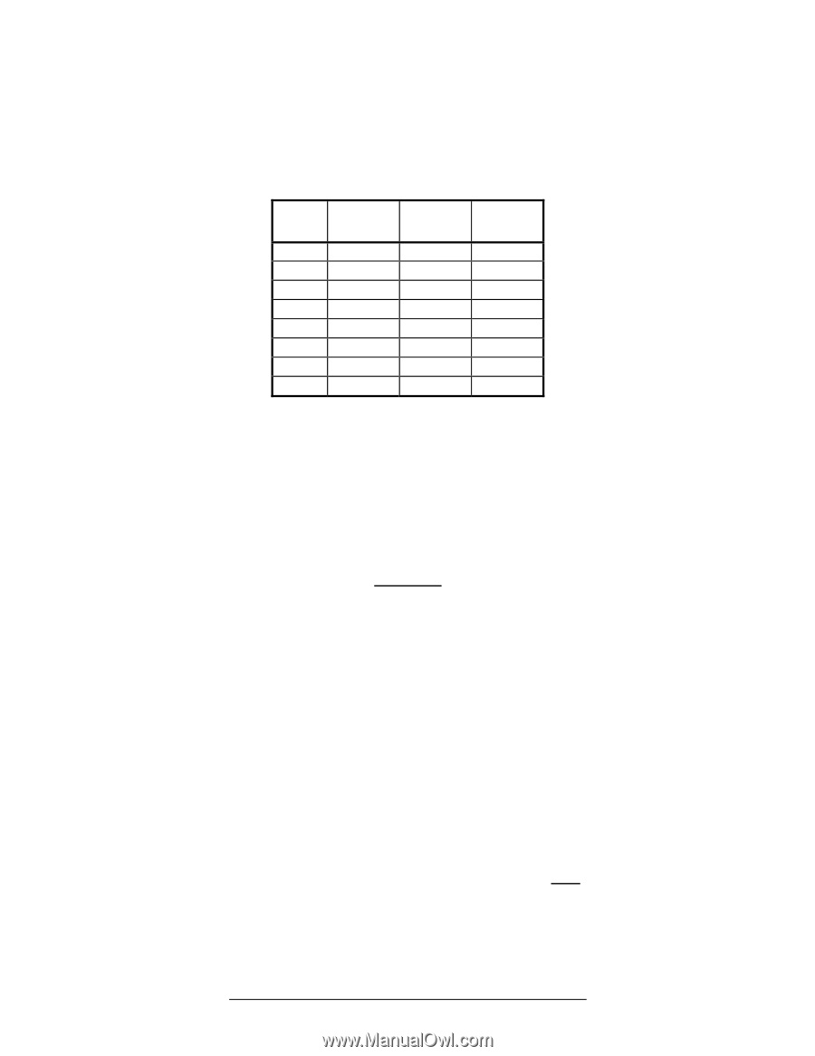
This pump can be controlled from third party pool controls as well as Hayward controls that are not software compatible using relay contacts to select the speeds set in the Timer Menu (see section 6.7). In addition to this section you may also consult the applicable pool control installation manual for electrical connection details. Once installed, Remote Control Mode must be set to Relay Control in the pump Configuration Menu (see section 6.6). Preset Speeds 1-4 and Quick Clean are disabled when the pump is remotely controlled. When inputs INP1-3 are activated via the pool control relay contacts, timer speeds 1-8 are selected according to the following table (see section 6.7): Timer Speed 1 2 3 4 5 6 7 8 INP1 Status OFF ON OFF ON OFF ON OFF ON INP2 Status OFF OFF ON ON OFF OFF ON ON INP3 Status OFF OFF OFF OFF ON ON ON ON The number of speeds available depends on the number of auxiliary relays used as noted below: 1. Filter pump relay plus 1 auxiliary relays allows control of 2 speeds 2. Filter pump relay plus 2 auxiliary relays allows control of 4 speeds 3. Filter pump relay plus 3 auxiliary relays allows control of 8 speeds 5.4. Wall Mounted Digital Control Interface Wiring (Optional) Figure 5.4-1 Connection wire must be rated for a minimum of 300V, and may be up to 500 feet in length. Use removable 4-position terminal block connectors for wiring connection to interface and motor drive PCB's taking care to note the wire colors and corresponding numbers next to the connectors. Terminal block must be installed with screws facing up to ensure proper connection. DIP switch #1 must be "ON". Page 17 of 36 USE ONLY HAYWARD GENUINE REPLACEMENT PARTS 2.70 THP VS Pump Family IS3206VSP3 Rev-B
-
 1
1 -
2
-
3
-
4
-
5
-
6
-
7
-
8
-
9
-
10
-
11
-
 12
12 -
 13
13 -
 14
14 -
 15
15 -
 16
16 -
 17
17 -
 18
18 -
 19
19 -
 20
20 -
 21
21 -
 22
22 -
23
-
24
-
25
-
26
-
27
-
28
-
29
-
30
-
31
-
32
-
33
-
34
-
35
-
36
 |
 |