Hayward W3SP3206VSP TriStar VS 950 - Owners Manual - Page 33
Check System Messages
 |
View all Hayward W3SP3206VSP manuals
Add to My Manuals
Save this manual to your list of manuals |
Page 33 highlights
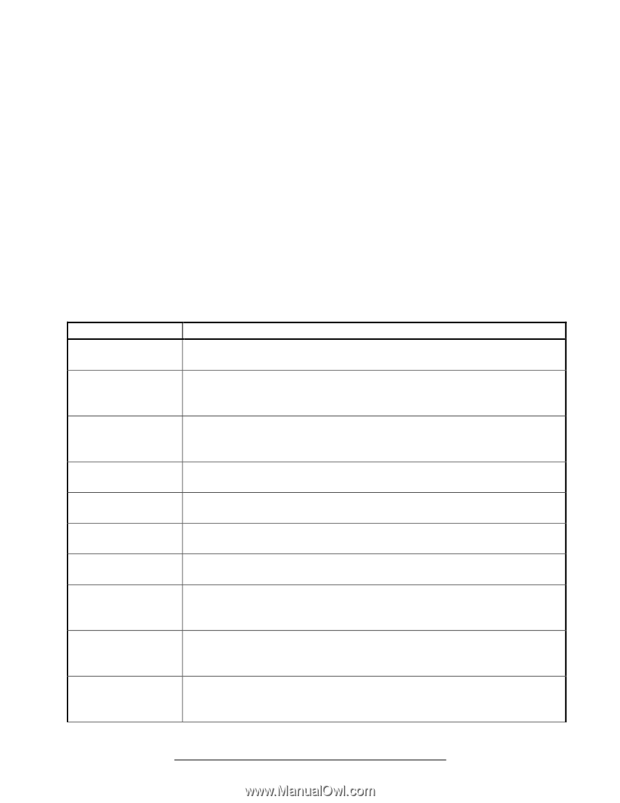
Noisy Pump: 1. Air leak in suction piping, cavitations caused by restricted or undersized suction line or leak at any joint, low water level in pool, and unrestricted discharge return lines. Correct the suction condition or throttle return lines, if practical. Holding your hand over the return fitting will sometimes prove this, or by putting in a smaller eyeball fitting. 2. Vibration due to improper mounting, etc. Mount the pump on a level surface and secure the pump to the equipment pad. 3. Foreign matter in the pump housing. Loose stones/debris hitting the impeller could be the cause. Clean the pump housing. 4. Motor bearings noisy from normal wear, rust, overheating, or concentration of chemicals causing seal damage, which will allow chlorinated water to seep into bearings wiping out the grease causing bearing to whine. All seal leaks should be replaced at once. Interference With Home Automation/Power Line Communication Equipment: 1. Make sure the terminal board connections agree with the wiring diagram on the pump data plate label. 2. Check for and correct any improper or loose wiring connections. 3. Install noise filter (from home automation/power line communication equipment vendor) to prevent equipment interference. 11.2. Check System Messages Code Troubleshooting Check System DC voltage too high Indicates that the internal DC bus voltage is too high. Verify that line voltage is within 10% of pump rated voltage at the terminal block. Check System DC voltage too low Indicates that the internal DC bus voltage is too low. Verify that line voltage is within 10% of pump rated voltage at the terminal block. Also, verify that power supply connections are properly made at the circuit breaker as well as at the terminal block. Check System Drive is overheated Indicates that the internal components of the drive have become overheated. Motor airflow path should be checked for obstructions and cleared if present. Check ambient temperature and verify against motor nameplate (50°C/122°F). Check System Drive overload Indicates that motor current is too high. Check impeller, diffuser, shaft seal, and motor for any issues or binding. Check System Indicates that the drive has lost control over motor shaft rotation. Check impeller, Pump has stalled diffuser, shaft seal, and motor for any issues or binding. Check System Pump failed to start Indicates that the drive was not able to start the motor. Check impeller, diffuser, shaft seal, and motor for any issues or binding. Check System Motor phase lost Indicates that one of the motor phases is open and that the motor/drive may need to be replaced. Contact Hayward Technical Service for additional assistance. Check System Processor failed Indicates that there is a problem with the processor in the motor/drive, and that the motor/drive may need to be replaced. Contact Hayward Technical Service for additional assistance. Check System Communication failed Indicates that there are communication problems between the user interface and motor/drive. Connections between the user interface and motor/drive should be verified. Check System Memory failed Indicates that the drive memory has been damaged or corrupted, and that the motor/drive may need to be replaced. Contact Hayward Technical Service for additional assistance. Page 33 of 36 USE ONLY HAYWARD GENUINE REPLACEMENT PARTS 2.70 THP VS Pump Family IS3206VSP3 Rev-B
-
 1
1 -
2
-
3
-
4
-
5
-
6
-
7
-
8
-
9
-
10
-
11
-
12
-
13
-
14
-
15
-
16
-
17
-
18
-
19
-
20
-
21
-
22
-
23
-
24
-
25
-
26
-
27
-
 28
28 -
 29
29 -
 30
30 -
 31
31 -
 32
32 -
 33
33 -
 34
34 -
 35
35 -
 36
36
 |
 |