HealthRider H70e Elliptical English Manual - Page 17
Maintenance And Troubleshooting
 |
View all HealthRider H70e Elliptical manuals
Add to My Manuals
Save this manual to your list of manuals |
Page 17 highlights
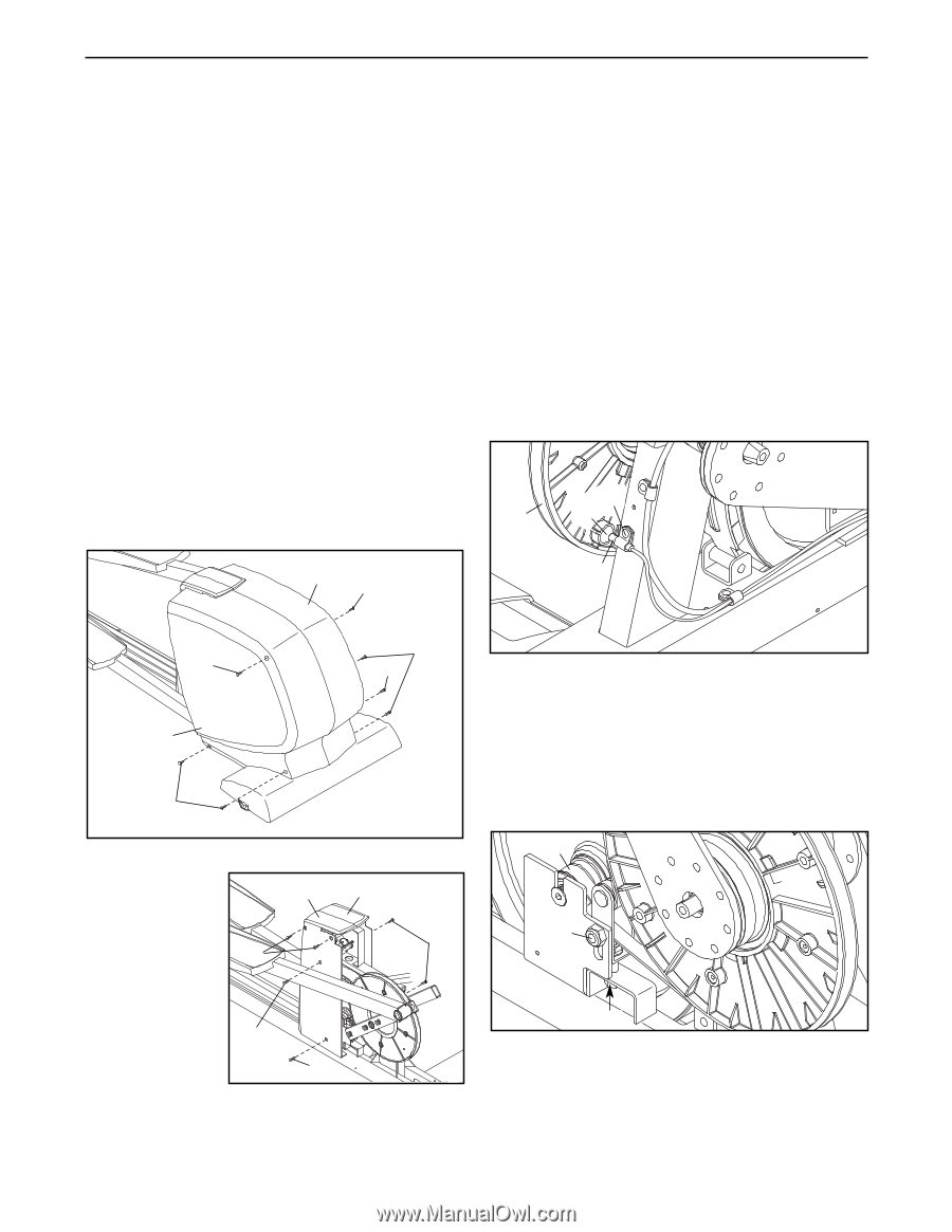
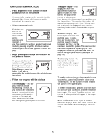
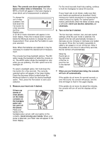
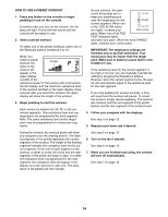
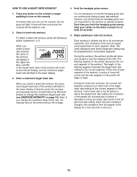
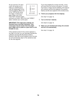
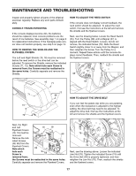
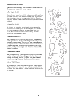
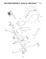
MAINTENANCE AND TROUBLESHOOTING Inspect and properly tighten all parts of the elliptical exerciser regularly. Replace any worn parts immediately. CONSOLE TROUBLESHOOTING If the console displays become dim, the batteries should be replaced; most console problems are the result of low batteries. See assembly step 7 on page 9 for replacement instructions. If the handgrip pulse sensor does not function properly, see step 5 on page 13. HOW TO REMOVE THE SHIELDS AND THE FLYWHEEL COVERS The Left and Right Shields (15, 16) must be removed before the reed switch or the drive belt can be adjusted. To remove the Shields, remove the indicated Screws (71, 72). Note which hole each Screw is removed from; the Screws must be reattached in the same holes. Carefully separate and remove the Shields. HOW TO ADJUST THE REED SWITCH If the console does not display correct feedback, the reed switch should be adjusted. To adjust the reed switch, first see the instructions at the left and remove the shields and the flywheel covers. Next, see the drawing below. Locate the Reed Switch (55). Turn the Pulley (38) until a Magnet (37) is aligned with the Reed Switch. Loosen, but do not remove, the indicated Screw (72). Slide the Reed Switch slightly closer to or away from the Magnet, and then retighten the Screw. Turn the Pulley for a moment. Repeat these actions until the console displays correct feedback. Then, reattach the shields and the flywheel covers. 72 38 37 16 71 55 71 15 72 72 48 HOW TO ADJUST THE DRIVE BELT If you can feel the pedals slip while you are pedaling, even when the resistance is adjusted to the highest setting, the drive belt may need to be adjusted. To adjust the drive belt, first see the instructions at the left and remove the shields and the flywheel covers. Next, the Right and Left 19 18 Flywheel Covers (18, 19) must be 69 removed. 48 Remove the indi- cated Screws (48, 69) from the Flywheel Covers. Note which 69 hole each Screw is 69 removed from; the Screws must be reattached in the same holes. Carefully separate and remove the Flywheel Covers. 39 76 74 Next, see the drawing above. Loosen the indicated Jam Nut (76). Tighten the indicated Screw (74) until the Drive Belt (39) is properly tightened, and then retighten the Jam Nut (76). Then, reattach the shields and the flywheel covers. 17
-
 1
1 -
2
-
3
-
4
-
5
-
6
-
7
-
8
-
9
-
10
-
11
-
 12
12 -
 13
13 -
 14
14 -
 15
15 -
 16
16 -
 17
17 -
 18
18 -
 19
19 -
 20
20 -
 21
21 -
 22
22 -
23
-
24
 |
 |