HP 1000-1200 Maintenance and Service Guide 1 - Page 47
Heat sink
 |
View all HP 1000-1200 manuals
Add to My Manuals
Save this manual to your list of manuals |
Page 47 highlights
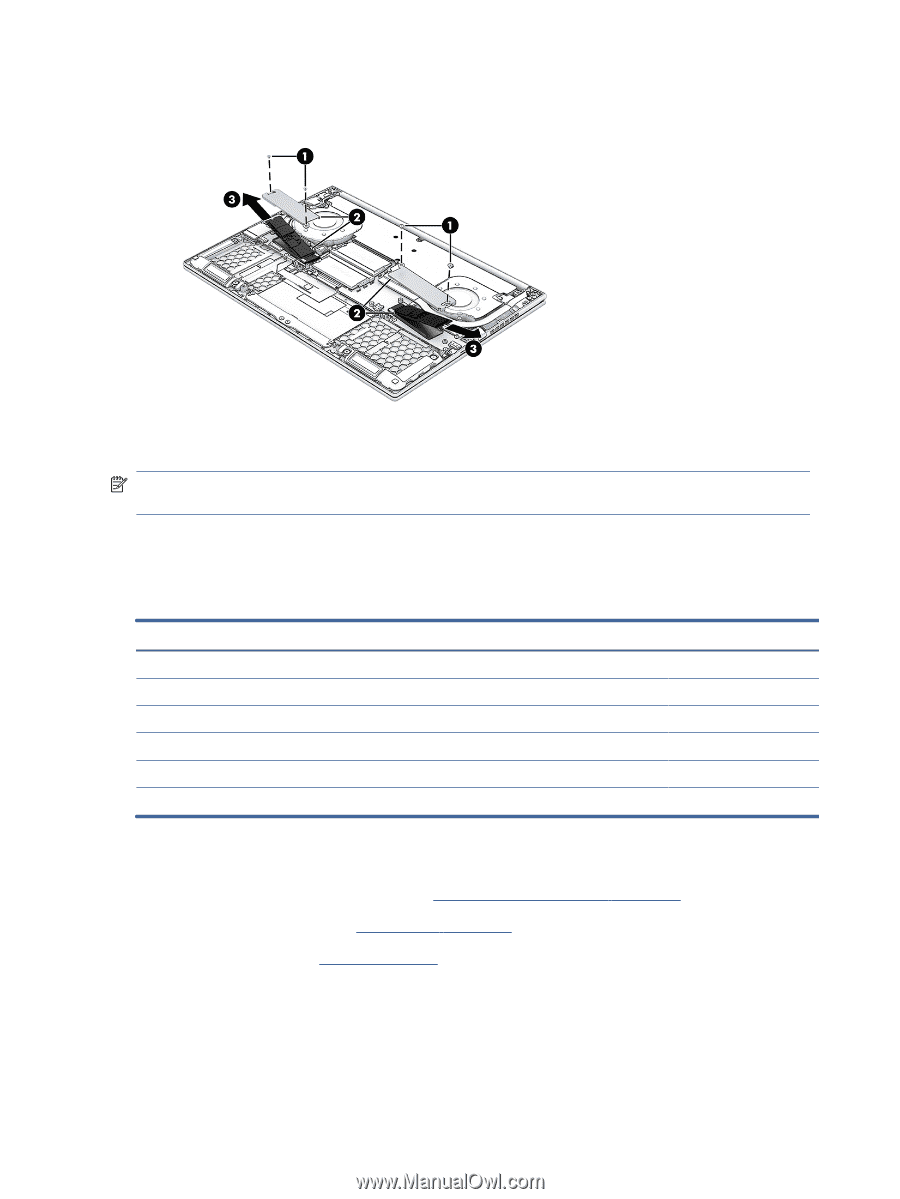
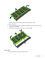
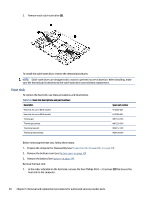
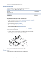
3. Remove each solid-state drive (3). To install the solid-state drive, reverse the removal procedures. NOTE: Solid-state drives are designed with a notch to prevent incorrect insertion. When installing, make sure the thermal pad is attached to the solid-state drive covers before replacement. Heat sink To remove the heat sink, use these procedures and illustrations. Table 5-6 Heat sink descriptions and part numbers Description Heat sink for use in 80 W models Heat sink for use in 60 W models Thermal gel Thermal gel syringe Thermal grease kit Thermal grease syringe Spare part number N13390-001 N13389-001 M81334-001 M81335-001 M28157-001 M28158-001 Before removing the heat sink, follow these steps: 1. Prepare the computer for disassembly (see Preparation for disassembly on page 33). 2. Remove the bottom cover (see Bottom cover on page 33). 3. Remove the battery (see Battery on page 34). Remove the heat sink: 1. In the order indicated on the heat sink, remove the four Phillips M2.0 × 3.5 screws (1) that secure the heat sink to the computer. 40 Chapter 5 Removal and replacement procedures for authorized service provider parts
-
 1
1 -
2
-
3
-
4
-
5
-
6
-
7
-
8
-
9
-
10
-
11
-
12
-
13
-
14
-
15
-
16
-
17
-
18
-
19
-
20
-
21
-
22
-
23
-
24
-
25
-
26
-
27
-
28
-
29
-
30
-
31
-
32
-
33
-
34
-
35
-
36
-
37
-
38
-
39
-
40
-
41
-
 42
42 -
 43
43 -
 44
44 -
 45
45 -
 46
46 -
 47
47 -
 48
48 -
 49
49 -
 50
50 -
 51
51 -
 52
52 -
53
-
54
-
55
-
56
-
57
-
58
-
59
-
60
-
61
-
62
-
63
-
64
-
65
-
66
-
67
-
68
-
69
-
70
-
71
-
72
-
73
-
74
-
75
-
76
-
77
-
78
-
79
-
80
-
81
-
82
-
83
-
84
-
85
-
86
-
87
-
88
-
89
-
90
 |
 |