HP 1155 Maintenance & Service Guide HP 1155 All-in-One Business PC - Page 80
System Board
 |
View all HP 1155 manuals
Add to My Manuals
Save this manual to your list of manuals |
Page 80 highlights
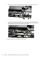
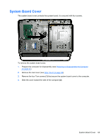
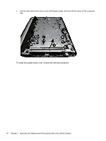
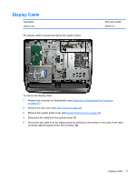
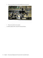
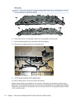
System Board Description System board with AMD E1-1500 processor, USB 3.0 (includes heat sink, gasket, processor, replacement thermal material) For use in models without Windows 8 For use in models with Windows Standard For use in models with Windows Professional Spare part number 703642-001 728286-001 728286-501 728286-601 The system board is secured with nine screws. To remove the system board: 1. Prepare the computer for disassembly (see Preparing to Disassemble the Computer on page 37). 2. Remove the rear cover (see Rear Cover on page 38). 3. Remove the system board cover (see System Board Cover on page 69). 4. Remove the memory module (see Memory on page 45). 5. Remove the WLAN module (see WLAN Module on page 47). 6. Disconnect all cables from the system board, noting their location for reinstallation. 7. Remove the nine screws (circled in image) that secure the system board to the computer. 8. Lift the system board straight up and out of the computer. To install the system board, reverse the removal procedures. System Board 73
-
 1
1 -
2
-
3
-
4
-
5
-
6
-
7
-
8
-
9
-
10
-
11
-
12
-
13
-
14
-
15
-
16
-
17
-
18
-
19
-
20
-
21
-
22
-
23
-
24
-
25
-
26
-
27
-
28
-
29
-
30
-
31
-
32
-
33
-
34
-
35
-
36
-
37
-
38
-
39
-
40
-
41
-
42
-
43
-
44
-
45
-
46
-
47
-
48
-
49
-
50
-
51
-
52
-
53
-
54
-
55
-
56
-
57
-
58
-
59
-
60
-
61
-
62
-
63
-
64
-
65
-
66
-
67
-
68
-
69
-
70
-
71
-
72
-
73
-
74
-
 75
75 -
 76
76 -
 77
77 -
 78
78 -
 79
79 -
 80
80 -
 81
81 -
 82
82 -
 83
83 -
 84
84 -
 85
85 -
86
-
87
-
88
-
89
-
90
-
91
-
92
-
93
-
94
-
95
-
96
-
97
-
98
-
99
-
100
-
101
-
102
-
103
-
104
-
105
-
106
-
107
-
108
-
109
-
110
-
111
-
112
-
113
-
114
-
115
-
116
-
117
-
118
-
119
-
120
-
121
-
122
-
123
-
124
-
125
-
126
-
127
-
128
-
129
-
130
-
131
-
132
-
133
-
134
-
135
-
136
-
137
-
138
-
139
-
140
-
141
-
142
-
143
-
144
-
145
-
146
-
147
-
148
-
149
 |
 |
