HP 12000 HP StorageWorks 12000 Gateway Virtual Library System User Guide (AH81 - Page 190
Ethernet Switch 2810–24G Components, LEDs, and Buttons
 |
View all HP 12000 manuals
Add to My Manuals
Save this manual to your list of manuals |
Page 190 highlights
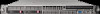
Item 6 7 8 9, 10 9, 11 Description Fan status LED Status Blinking green1 = The cooling fan has failed. The switch Fault LED will be blinking simultaneously. Off = The cooling fan is operating normally. Mode select button Press the button to step from one mode to the next. The current mode setting is indicated by the Mode select LEDs near the button. Mode select LEDs Act = Indicates that the port Mode LEDs are displaying network activity information. FDx = Indicates that the port Mode LEDs are lit for ports that are in Full Duplex Mode. Spd = Indicates that the port Mode LEDs are lit for ports that are operating at their maximum possible link speed. For the 10/100TX ports, that is 100 Mbps. ! = Indicates that the port Mode LEDs are displaying network events that could require operator attention, for example CRC errors or late collisions. Link LED On = Indicates the port is enabled and receiving a link indication from the connected device. Off = One of these conditions exists: • No active network cable is connected to the port • The port is not receiving link beat or sufficient light • The port has been disabled through the switch console, the web browser interface, or HP TopTools. Blinking = If the LED is blinking simultaneously with the Fault LED, the corresponding port has failed its self test. Mode LED Displays network activity information, or whether the port is configured for Full Duplex operation, or maximum link speed operation, or is experiencing network events requiring operator intervention depending on the mode selected. • If the Activity (Act) indicator LED is lit, each Mode LED displays activity information for the associated port-it flickers as network traffic is received and transmitted through the port. • If the Full Duplex (FDx) indicator LED is lit, the Mode LEDs light for those ports that are operating in full duplex. • If the maximum speed (Max) indicator LED is lit, the Mode LEDs light for those ports that are operating at their maximum possible link speed: 100 Mbps for 10/100 ports and 100-FX fiber-optic ports, and 1000 Mbps for 100/1000Base-T or gigabit fiber-optic ports. • If the attention (!) indicator LED is lit, each Mode LED lights briefly for each network event that could require operator attention, for example, late collisions or CRC errors. 1The blinking behavior is an on/off cycle once every 1.6 seconds, approximately. Ethernet Switch 2810-24G Components, LEDs, and Buttons This section provides images and descriptions of the front and rear panels of the Ethernet Switch 2810-24G. 190 Component Identification
-
 1
1 -
2
-
3
-
4
-
5
-
6
-
7
-
8
-
9
-
10
-
11
-
12
-
13
-
14
-
15
-
16
-
17
-
18
-
19
-
20
-
21
-
22
-
23
-
24
-
25
-
26
-
27
-
28
-
29
-
30
-
31
-
32
-
33
-
34
-
35
-
36
-
37
-
38
-
39
-
40
-
41
-
42
-
43
-
44
-
45
-
46
-
47
-
48
-
49
-
50
-
51
-
52
-
53
-
54
-
55
-
56
-
57
-
58
-
59
-
60
-
61
-
62
-
63
-
64
-
65
-
66
-
67
-
68
-
69
-
70
-
71
-
72
-
73
-
74
-
75
-
76
-
77
-
78
-
79
-
80
-
81
-
82
-
83
-
84
-
85
-
86
-
87
-
88
-
89
-
90
-
91
-
92
-
93
-
94
-
95
-
96
-
97
-
98
-
99
-
100
-
101
-
102
-
103
-
104
-
105
-
106
-
107
-
108
-
109
-
110
-
111
-
112
-
113
-
114
-
115
-
116
-
117
-
118
-
119
-
120
-
121
-
122
-
123
-
124
-
125
-
126
-
127
-
128
-
129
-
130
-
131
-
132
-
133
-
134
-
135
-
136
-
137
-
138
-
139
-
140
-
141
-
142
-
143
-
144
-
145
-
146
-
147
-
148
-
149
-
150
-
151
-
152
-
153
-
154
-
155
-
156
-
157
-
158
-
159
-
160
-
161
-
162
-
163
-
164
-
165
-
166
-
167
-
168
-
169
-
170
-
171
-
172
-
173
-
174
-
175
-
176
-
177
-
178
-
179
-
180
-
181
-
182
-
183
-
184
-
 185
185 -
 186
186 -
 187
187 -
 188
188 -
 189
189 -
 190
190 -
 191
191 -
 192
192 -
 193
193 -
 194
194 -
 195
195 -
196
-
197
-
198
-
199
-
200
-
201
-
202
-
203
-
204
-
205
-
206
-
207
-
208
-
209
-
210
-
211
-
212
-
213
-
214
-
215
-
216
-
217
-
218
-
219
-
220
-
221
-
222
-
223
-
224
-
225
-
226
-
227
-
228
-
229
-
230
-
231
-
232
-
233
-
234
-
235
-
236
-
237
-
238
-
239
-
240
-
241
-
242
-
243
-
244
-
245
-
246
-
247
-
248
-
249
-
250
-
251
-
252
-
253
-
254
-
255
-
256
-
257
-
258
-
259
-
260
-
261
-
262
-
263
-
264
 |
 |
