HP 14-w000 14 Notebook PC Maintenance and Service Guide - Page 45
Swing the keyboard, by lifting connector tab and then disconnecting the keyboard cable
 |
View all HP 14-w000 manuals
Add to My Manuals
Save this manual to your list of manuals |
Page 45 highlights
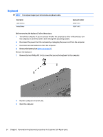
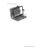
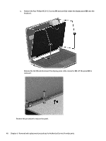
4. Insert a thin tool or a keyboard push tool into the left retention screw hole, and then press on the back of the keyboard until the keyboard disengages from the computer. 5. Position the computer right-side up with the front toward you. 6. Gently slide your finger along the top edge of the keyboard to release the keyboard clips (1). Lift up the rear edge of the keyboard (2). 7. Swing the keyboard (1) up and forward until it rests upside down on the palm rest. Release the ZIF connector (2) by lifting connector tab and then disconnecting the keyboard cable (3) from the system board. Component replacement procedures 35
-
 1
1 -
2
-
3
-
4
-
5
-
6
-
7
-
8
-
9
-
10
-
11
-
12
-
13
-
14
-
15
-
16
-
17
-
18
-
19
-
20
-
21
-
22
-
23
-
24
-
25
-
26
-
27
-
28
-
29
-
30
-
31
-
32
-
33
-
34
-
35
-
36
-
37
-
38
-
39
-
 40
40 -
 41
41 -
 42
42 -
 43
43 -
 44
44 -
 45
45 -
 46
46 -
 47
47 -
 48
48 -
 49
49 -
 50
50 -
51
-
52
-
53
-
54
-
55
-
56
-
57
-
58
-
59
-
60
-
61
-
62
-
63
-
64
-
65
-
66
-
67
-
68
-
69
-
70
-
71
-
72
-
73
-
74
-
75
-
76
-
77
-
78
-
79
-
80
-
81
-
82
-
83
-
84
-
85
-
86
-
87
-
88
-
89
-
90
-
91
-
92
-
93
-
94
-
95
-
96
-
97
-
98
-
99
 |
 |

4.
Insert a thin tool or a keyboard push tool into the left retention screw hole, and then press on the back
of the keyboard until the keyboard disengages from the computer.
5.
Position the computer right-side up with the front toward you.
6.
Gently slide your finger along the top edge of the keyboard to release the keyboard clips
(1)
. Lift up the
rear edge of the keyboard
(2)
.
7.
Swing the keyboard
(1)
up and forward until it rests upside down on the palm rest. Release the ZIF
connector
(2)
by lifting connector tab and then disconnecting the keyboard cable
(3)
from
the system board.
Component replacement procedures
35