HP 14-w000 14 Notebook PC Maintenance and Service Guide - Page 50
and carefully rotate the display panel, Lift the panel
 |
View all HP 14-w000 manuals
Add to My Manuals
Save this manual to your list of manuals |
Page 50 highlights
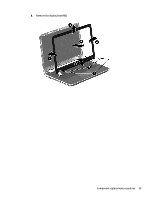
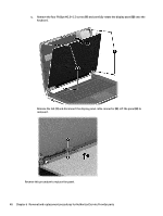
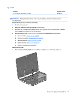
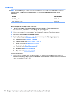
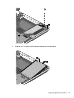
c. Remove the four Phillips M2.0×2.5 screws (1) and carefully rotate the display panel (2) onto the keyboard. Release the tab (1) and disconnect the display panel cable connector (2). Lift the panel (3) to remove it. Reverse this procedure to replace the panel. 40 Chapter 6 Removal and replacement procedures for Authorized Service Provider parts
-
 1
1 -
2
-
3
-
4
-
5
-
6
-
7
-
8
-
9
-
10
-
11
-
12
-
13
-
14
-
15
-
16
-
17
-
18
-
19
-
20
-
21
-
22
-
23
-
24
-
25
-
26
-
27
-
28
-
29
-
30
-
31
-
32
-
33
-
34
-
35
-
36
-
37
-
38
-
39
-
40
-
41
-
42
-
43
-
44
-
 45
45 -
 46
46 -
 47
47 -
 48
48 -
 49
49 -
 50
50 -
 51
51 -
 52
52 -
 53
53 -
 54
54 -
 55
55 -
56
-
57
-
58
-
59
-
60
-
61
-
62
-
63
-
64
-
65
-
66
-
67
-
68
-
69
-
70
-
71
-
72
-
73
-
74
-
75
-
76
-
77
-
78
-
79
-
80
-
81
-
82
-
83
-
84
-
85
-
86
-
87
-
88
-
89
-
90
-
91
-
92
-
93
-
94
-
95
-
96
-
97
-
98
-
99
 |
 |

c.
Remove the four Phillips M2.0×2.5 screws
(1)
and carefully rotate the display panel
(2)
onto the
keyboard.
Release the tab
(1)
and disconnect the display panel cable connector
(2)
. Lift the panel
(3)
to
remove it.
Reverse this procedure to replace the panel.
40
Chapter 6
Removal and replacement procedures for Authorized Service Provider parts