HP 14-w000 14 Notebook PC Maintenance and Service Guide - Page 76
Keyboard see
 |
View all HP 14-w000 manuals
Add to My Manuals
Save this manual to your list of manuals |
Page 76 highlights
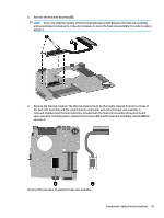
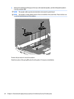
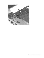
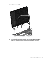
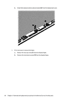
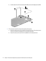
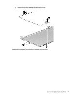
Display assembly subcomponents NOTE: These procedures are for replacing the display assembly internal components. The display is spared only at the subcomponent level. Component Webcamera/microphone module (includes adhesive and screws) Display panel cable (includes webcamera/microphone module cable and screws) Antenna Kit (includes screw and Mylar tape) Display Hinge Kit (includes left and right hinges and screws) Display back cover (includes screws): Spare part number 776787-001 734407-001 788630-001 734408-001 785282-001 Before removing the display assembly subcomponents, follow these steps: 1. Turn off the computer. If you are unsure whether the computer is off or in Hibernation, turn the computer on, and then shut it down through the operating system. 2. Disconnect the power from the computer by unplugging the power cord from the computer. 3. Disconnect all external devices from the computer. 4. Remove the battery (see Battery on page 25), and then remove the following components: a. Service door (see Service door on page 26) b. Memory module (see Memory module on page 28) c. WLAN module (see WLAN module on page 30) d. Optical drive (see Optical drive on page 32) e. Keyboard (see Keyboard on page 34) f. Top cover (see Top cover on page 41) g. Hard drive (see Hard drive on page 44) h. System board (see System board on page 52) Remove the display assembly subcomponents: 1. Remove the display by removing the five Phillips PM2.5×6.5 screws (1) that secure the display assembly to the base enclosure. 66 Chapter 6 Removal and replacement procedures for Authorized Service Provider parts
-
 1
1 -
2
-
3
-
4
-
5
-
6
-
7
-
8
-
9
-
10
-
11
-
12
-
13
-
14
-
15
-
16
-
17
-
18
-
19
-
20
-
21
-
22
-
23
-
24
-
25
-
26
-
27
-
28
-
29
-
30
-
31
-
32
-
33
-
34
-
35
-
36
-
37
-
38
-
39
-
40
-
41
-
42
-
43
-
44
-
45
-
46
-
47
-
48
-
49
-
50
-
51
-
52
-
53
-
54
-
55
-
56
-
57
-
58
-
59
-
60
-
61
-
62
-
63
-
64
-
65
-
66
-
67
-
68
-
69
-
70
-
 71
71 -
 72
72 -
 73
73 -
 74
74 -
 75
75 -
 76
76 -
 77
77 -
 78
78 -
 79
79 -
 80
80 -
 81
81 -
82
-
83
-
84
-
85
-
86
-
87
-
88
-
89
-
90
-
91
-
92
-
93
-
94
-
95
-
96
-
97
-
98
-
99
 |
 |
