HP 14-y000 14 Notebook PC Maintenance and Service Guide - Page 51
Top cover, WLAN module see
 |
View all HP 14-y000 manuals
Add to My Manuals
Save this manual to your list of manuals |
Page 51 highlights
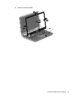
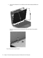
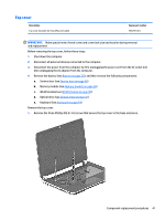
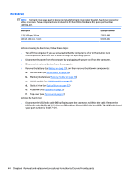
Top cover Description Top cover (includes the TouchPad and cable) Spare part number 785295-001 IMPORTANT: Make special note of each screw and screw lock size and location during removal and replacement Before removing the top cover, follow these steps: 1. Shut down the computer. 2. Disconnect all external devices connected to the computer. 3. Disconnect the power from the computer by first unplugging the power cord from the AC outlet and then unplugging the AC adapter from the computer. 4. Remove the battery (see Battery on page 25), and then remove the following components: a. Service door (see Service door on page 26) b. Memory module (see Memory module on page 28) c. WLAN module (see WLAN module on page 30) d. Optical drive (see Optical drive on page 32) e. Keyboard (see Keyboard on page 34) Remove the top cover: 1. Remove the three Phillips M2.5×3.0 screws that secure the top cover to the base enclosure. Component replacement procedures 41
-
 1
1 -
2
-
3
-
4
-
5
-
6
-
7
-
8
-
9
-
10
-
11
-
12
-
13
-
14
-
15
-
16
-
17
-
18
-
19
-
20
-
21
-
22
-
23
-
24
-
25
-
26
-
27
-
28
-
29
-
30
-
31
-
32
-
33
-
34
-
35
-
36
-
37
-
38
-
39
-
40
-
41
-
42
-
43
-
44
-
45
-
 46
46 -
 47
47 -
 48
48 -
 49
49 -
 50
50 -
 51
51 -
 52
52 -
 53
53 -
 54
54 -
 55
55 -
 56
56 -
57
-
58
-
59
-
60
-
61
-
62
-
63
-
64
-
65
-
66
-
67
-
68
-
69
-
70
-
71
-
72
-
73
-
74
-
75
-
76
-
77
-
78
-
79
-
80
-
81
-
82
-
83
-
84
-
85
-
86
-
87
-
88
-
89
-
90
-
91
-
92
-
93
-
94
-
95
-
96
-
97
-
98
-
99
 |
 |
