HP 15-ay100 17-x099 Models: 17-x100 - 17-x199 - Maintenance and Service Guide - Page 78
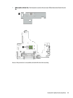
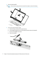
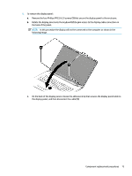
Position the computer with the display open and hanging down
 |
View all HP 15-ay100 manuals
Add to My Manuals
Save this manual to your list of manuals |
Page 78 highlights
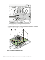
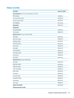
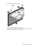
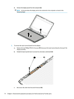
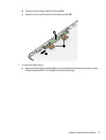
Description HD VGA Touch control board Spare part number 709372-032 766523-021 856600-001 Before removing the display assembly, follow these steps: 1. Shut down the computer. If you are unsure whether the computer is off or in Hibernation, turn the computer on, and then shut it down through the operating system. 2. Disconnect all external devices connected to the computer. 3. Disconnect the power from the computer by first unplugging the power cord from the AC outlet and then unplugging the AC adapter from the computer. 4. Remove the battery (see Battery on page 34). 5. Remove the optical drive (see Optical drive on page 35). 6. Remove the bottom cover (see Bottom cover on page 41). 7. Remove the fan/heat sink (see Fan/heat sink assembly on page 58). To remove the display assembly: 1. Position the computer with the display open and hanging down off the edge of a table. 2. Disconnect the display cable from the system board (1). 3. Disconnect the wireless antenna cables from the WLAN module (2). 4. Remove the two Phillips PM2.5×7.0 screws (3) that secure the display assembly to the computer. 5. Remove the three Phillips broadhead PM2.0×2.0 screws (4) that secure the display assembly to the computer. 6. Open the display to rotate the hinges upward to an angle (5). 70 Chapter 6 Removal and replacement procedures for Authorized Service Provider parts
-
 1
1 -
2
-
3
-
4
-
5
-
6
-
7
-
8
-
9
-
10
-
11
-
12
-
13
-
14
-
15
-
16
-
17
-
18
-
19
-
20
-
21
-
22
-
23
-
24
-
25
-
26
-
27
-
28
-
29
-
30
-
31
-
32
-
33
-
34
-
35
-
36
-
37
-
38
-
39
-
40
-
41
-
42
-
43
-
44
-
45
-
46
-
47
-
48
-
49
-
50
-
51
-
52
-
53
-
54
-
55
-
56
-
57
-
58
-
59
-
60
-
61
-
62
-
63
-
64
-
65
-
66
-
67
-
68
-
69
-
70
-
71
-
72
-
 73
73 -
 74
74 -
 75
75 -
 76
76 -
 77
77 -
 78
78 -
 79
79 -
 80
80 -
 81
81 -
 82
82 -
 83
83 -
84
-
85
-
86
-
87
-
88
-
89
-
90
-
91
-
92
-
93
-
94
-
95
-
96
-
97
-
98
-
99
-
100
-
101
-
102
-
103
-
104
-
105
-
106
-
107
-
108
-
109
-
110
-
111
-
112
-
113
-
114
 |
 |