HP 15-ay100 17-x099 Models: 17-x100 - 17-x199 - Maintenance and Service Guide - Page 85
display/webcam cable, as shown in the following image.
 |
View all HP 15-ay100 manuals
Add to My Manuals
Save this manual to your list of manuals |
Page 85 highlights
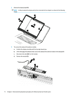
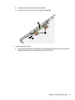
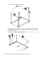
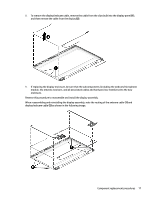
8. To remove the display/webcam cable, remove the cable from the clips built into the display panel (1), and then remove the cable from the display (2). 9. If replacing the display enclosure, be sure that the subcomponents (including the webcam/microphone module, the antenna receivers, and all associated cables and hardware) are transferred to the new enclosure. Reverse this procedure to reassemble and install the display assembly. When reassembling and reinstalling the display assembly, note the routing of the antenna cable (1) and display/webcam cable (2) as shown in the following image. Component replacement procedures 77
-
 1
1 -
2
-
3
-
4
-
5
-
6
-
7
-
8
-
9
-
10
-
11
-
12
-
13
-
14
-
15
-
16
-
17
-
18
-
19
-
20
-
21
-
22
-
23
-
24
-
25
-
26
-
27
-
28
-
29
-
30
-
31
-
32
-
33
-
34
-
35
-
36
-
37
-
38
-
39
-
40
-
41
-
42
-
43
-
44
-
45
-
46
-
47
-
48
-
49
-
50
-
51
-
52
-
53
-
54
-
55
-
56
-
57
-
58
-
59
-
60
-
61
-
62
-
63
-
64
-
65
-
66
-
67
-
68
-
69
-
70
-
71
-
72
-
73
-
74
-
75
-
76
-
77
-
78
-
79
-
 80
80 -
 81
81 -
 82
82 -
 83
83 -
 84
84 -
 85
85 -
 86
86 -
 87
87 -
 88
88 -
 89
89 -
 90
90 -
91
-
92
-
93
-
94
-
95
-
96
-
97
-
98
-
99
-
100
-
101
-
102
-
103
-
104
-
105
-
106
-
107
-
108
-
109
-
110
-
111
-
112
-
113
-
114
 |
 |
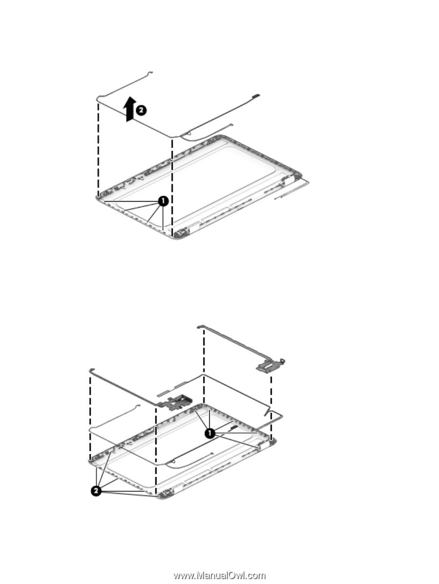
8.
To remove the display/webcam cable, remove the cable from the clips built into the display panel
(1)
,
and then remove the cable from the display
(2)
.
9.
If replacing the display enclosure, be sure that the subcomponents (including the webcam/microphone
module, the antenna receivers, and all associated cables and hardware) are transferred to the new
enclosure.
Reverse this procedure to reassemble and install the display assembly.
When reassembling and reinstalling the display assembly, note the routing of the antenna cable
(1)
and
display/webcam cable
(2)
as shown in the following image.
Component replacement procedures
77