HP 6125XLG R2306-HP 6125XLG Blade Switch EVB Configuration Guide - Page 12
Activating a VSI, Displaying and maintaining EVB, EVB configuration example, Network requirements - irf
 |
View all HP 6125XLG manuals
Add to My Manuals
Save this manual to your list of manuals |
Page 12 highlights
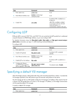
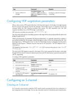
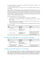
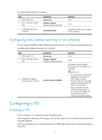
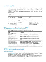
Activating a VSI Configurations such as traffic policing for a VSI (see ACL and QoS Configuration Guide) take effect only after the VSI is activated. When a VSI is not activated, do not make any configuration except for VSI filter configuration for the VSI. To activate a VSI, you must first configure a VSI filter. To remove a VSI filter for a VSI, you must first deactivate the VSI. To activate a VSI: Step 1. Enter system view. 2. Enter VSI view. 3. Activate the VSI. 4. (Optional.) Configure a description for the VSI. Command system-view interface s-channel interface-number:channel-id.vsi-lo cal-id evb vsi active description text Remarks N/A N/A By default, no VSI is activated. The default description information is "interface name Interface." Displaying and maintaining EVB Execute display commands in any view and the reset command in user view. Task Display CDCP negotiation information. Display S-channel EVB TLV negotiation information. Display S-channel information. Display EVB summary. Display VSI information. Display information about an S-channel interface or a VSI. Clear statistics for an S-channel interface or a VSI. Command display evb cdcp [ interface interface-type interface-number ] display evb evb-tlv [ interface interface-type interface-number ] display evb s-channel [ interface interface-type interface-number ] display evb summary display evb vsi [ verbose ] [ interface interface-type interface-number ] display interface [ s-channel [ interface-number:channel-id | interface-number:channel-id.vsi-local-id ] ] [ brief [ description ] ] reset counters interface [ s-channel [ interface-number:channel-id | interface-number:channel-id.vsi-local-id ] ] EVB configuration example Network requirements As shown in Figure 3, the Layer 2 network of a data center comprises two switches that form an IRF fabric, four EVB bridges, and four EVB stations. They communicate within VLAN 100. Create VM 1 with a MAC address of 0050-5684-21C7 on EVB station 1, and set VM1 as the FTP server with a CIR of 2048 kbps and a PIR of 4096 kbps. Only the R&D center is allowed to access the network. 9
-
 1
1 -
2
-
3
-
4
-
5
-
6
-
 7
7 -
 8
8 -
 9
9 -
 10
10 -
 11
11 -
 12
12 -
 13
13 -
 14
14 -
 15
15 -
 16
16 -
 17
17 -
18
-
19
-
20
-
21
 |
 |