HP 6125XLG R2306-HP 6125XLG Blade Switch EVB Configuration Guide - Page 5
Basic concepts, EVB working mechanism
 |
View all HP 6125XLG manuals
Add to My Manuals
Save this manual to your list of manuals |
Page 5 highlights
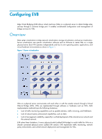
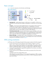
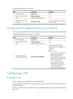
Basic concepts Figure 2 shows the components on the EVB station and EVB bridge. Figure 2 EVB architecture • Edge Relay (ER)-Transfers packets between one URP and one or more DRPs. An ER has one or more DRPs and one URP. Both URP and DRPs are called ER ports. An EVB station can have multiple ERs. • S-channel-A point-to-point S-VLAN established between a Port-mapping S-VLAN component in an EVB station and a Port-mapping S-VLAN component in an EVB bridge. An S-channel corresponds to the URP of an ER. On an EVB bridge, the end point of an S-channel is known as an S-channel interface. An S-channel is identified by the S-VLAN Identifier (SVID) and the S-channel Identifier (SCID), and the two values together are called an (SCID, SVID) pair. • Virtual Station Interface (VSI)-A port on a VM that directly connects to the DRP of an ER. A VSI is associated with a logical entity called VSI instance, which is identified by the VSI Instance Identifier (VSIID). A VSI is associated with the EVB bridge port to implement VM traffic management and policy configuration. A VSI can be considered as a subinterface of an S-channel. • Reflective Relay (RR)-An operation mode in which a received frame on a port that supports this function can be forwarded out of the same port. The EVB bridge uses this mode to forward traffic among VMs on an EVB station, as shown in Figure 2. EVB working mechanism An EVB station and an EVB bridge go through the following steps to implement VM traffic management: 1. Use the S-channel Discovery and Configuration Protocol (CDCP) to establish an S-channel. CDCP is used to configure S-channels between stations and bridges. When a station creates or deletes an S-channel, CDCP sends a CDCP TLV in an LLDP packet that is addressed using the Nearest non-TPMR Bridge address to the bridge. The bridge creates or deletes the S-channel. 2. Exchange EVB TLVs through LLDP to negotiate EVB capabilities for the S-channel, such as RR, ECP parameters, and VDP parameters. 3. Use the VSI Discovery and Configuration Protocol (VDP) to associate the VSIs of VMs with the bridge port. The bridge uses the VSIs to manage traffic for VMs. VDP manages the association between a VSI and a station-facing bridge port (SBP) on a bridge. VDP uses the Edge Control Protocol (ECP) to carry VDP TLVs. A VDP TLV comprises the VSIID, VSI type, and VSI version. 2
-
 1
1 -
 2
2 -
 3
3 -
 4
4 -
 5
5 -
 6
6 -
 7
7 -
 8
8 -
 9
9 -
 10
10 -
 11
11 -
12
-
13
-
14
-
15
-
16
-
17
-
18
-
19
-
20
-
21
 |
 |
