HP AE370A Brocade Web Tools Administrator's Guide v6.0.0 (53-1000606-01, April - Page 167
Viewing the temperature status, Fan States window
 |
UPC - 882780362611
View all HP AE370A manuals
Add to My Manuals
Save this manual to your list of manuals |
Page 167 highlights
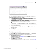
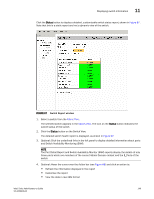
Displaying switch information 11 FIGURE 64 Fan States window The Fan No. column indicates either the fan number or the fan FRU number, depending on the switch model. A fan FRU can contain one or more fans. • For Brocade 48000 directors and Brocade 4100, 4900, 5000, and 7500 switches, the Fan No. column indicates the fan FRU number. • The Brocade 200E, 4012, 4016, 4018, 4020, and 4024 switches do not contain fan FRUs, so for these switch models, the Fan No. column indicates the fan number. NOTE For these switches, if the Fan Status window has no "Fan Speed" column, the speed is not monitored. 1. Select a switch from the Fabric Tree. The selected switch appears in the Switch View. The icon on the Fan button indicates the overall status of the fan. 2. Click the Fan button. The detailed fan status for the switch is displayed, as shown in Figure 64. Viewing the temperature status The icon on the Temp button indicates the overall status of the temperature. For more information regarding switch temperature, refer to the appropriate hardware documentation. 1. Select a switch from the Fabric Tree. The selected switch appears in the Switch View. The icon on the Temp button indicates the overall status of the temperature. 2. Click the Temp button on the Switch View. The detailed temperature sensor states for the switch are displayed, as shown in Figure 65. Web Tools Administrator's Guide 147 53-1000606-01
-
 1
1 -
2
-
3
-
4
-
5
-
6
-
7
-
8
-
9
-
10
-
11
-
12
-
13
-
14
-
15
-
16
-
17
-
18
-
19
-
20
-
21
-
22
-
23
-
24
-
25
-
26
-
27
-
28
-
29
-
30
-
31
-
32
-
33
-
34
-
35
-
36
-
37
-
38
-
39
-
40
-
41
-
42
-
43
-
44
-
45
-
46
-
47
-
48
-
49
-
50
-
51
-
52
-
53
-
54
-
55
-
56
-
57
-
58
-
59
-
60
-
61
-
62
-
63
-
64
-
65
-
66
-
67
-
68
-
69
-
70
-
71
-
72
-
73
-
74
-
75
-
76
-
77
-
78
-
79
-
80
-
81
-
82
-
83
-
84
-
85
-
86
-
87
-
88
-
89
-
90
-
91
-
92
-
93
-
94
-
95
-
96
-
97
-
98
-
99
-
100
-
101
-
102
-
103
-
104
-
105
-
106
-
107
-
108
-
109
-
110
-
111
-
112
-
113
-
114
-
115
-
116
-
117
-
118
-
119
-
120
-
121
-
122
-
123
-
124
-
125
-
126
-
127
-
128
-
129
-
130
-
131
-
132
-
133
-
134
-
135
-
136
-
137
-
138
-
139
-
140
-
141
-
142
-
143
-
144
-
145
-
146
-
147
-
148
-
149
-
150
-
151
-
152
-
153
-
154
-
155
-
156
-
157
-
158
-
159
-
160
-
161
-
 162
162 -
 163
163 -
 164
164 -
 165
165 -
 166
166 -
 167
167 -
 168
168 -
 169
169 -
 170
170 -
 171
171 -
 172
172 -
173
-
174
-
175
-
176
-
177
-
178
-
179
-
180
-
181
-
182
-
183
-
184
-
185
-
186
-
187
-
188
-
189
-
190
-
191
-
192
-
193
-
194
-
195
-
196
-
197
-
198
-
199
-
200
-
201
-
202
-
203
-
204
-
205
-
206
-
207
-
208
-
209
-
210
-
211
-
212
-
213
-
214
-
215
-
216
-
217
-
218
-
219
-
220
-
221
-
222
-
223
-
224
-
225
-
226
-
227
-
228
-
229
-
230
-
231
-
232
-
233
-
234
-
235
-
236
-
237
-
238
-
239
-
240
-
241
-
242
-
243
-
244
-
245
-
246
-
247
-
248
-
249
-
250
-
251
-
252
-
253
-
254
-
255
-
256
-
257
-
258
-
259
-
260
-
261
-
262
-
263
-
264
-
265
-
266
-
267
-
268
-
269
-
270
-
271
-
272
 |
 |
