HP Chromebook x360 14 G1 Maintenance and Service Guide - Page 41
Lock bracket, Remove the lock bracket
 |
View all HP Chromebook x360 14 G1 manuals
Add to My Manuals
Save this manual to your list of manuals |
Page 41 highlights
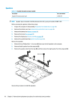
Lock bracket Table 5-10 Lock bracket description and part number Description Lock bracket Spare part number L36911-001 Before removing the lock bracket, follow these steps: 1. Prepare the computer for disassembly (Preparation for disassembly on page 20). 2. Remove the bottom cover (see Computer feet and bottom cover on page 20). 3. Remove the battery (see Battery on page 22). 4. Remove the I/O board (see USB bracket, I/O board on page 34). Remove the lock bracket: 1. Remove the Phillips M2.5 × 3.0 screw (1) that secures the lock bracket to the computer. 2. Remove the lock bracket (2). Reverse this procedure to install the lock bracket. Component replacement procedures 35
-
 1
1 -
2
-
3
-
4
-
5
-
6
-
7
-
8
-
9
-
10
-
11
-
12
-
13
-
14
-
15
-
16
-
17
-
18
-
19
-
20
-
21
-
22
-
23
-
24
-
25
-
26
-
27
-
28
-
29
-
30
-
31
-
32
-
33
-
34
-
35
-
 36
36 -
 37
37 -
 38
38 -
 39
39 -
 40
40 -
 41
41 -
 42
42 -
 43
43 -
 44
44 -
 45
45 -
 46
46 -
47
-
48
-
49
-
50
-
51
-
52
-
53
-
54
-
55
-
56
-
57
 |
 |

Lock bracket
Table 5-10
Lock bracket description and part number
Description
Spare part number
Lock bracket
L36911-001
Before removing the lock bracket, follow these steps:
1.
Prepare the computer for disassembly (
Preparation for disassembly
on page
20
).
2.
Remove the bottom cover (see
Computer feet and bottom cover
on page
20
).
3.
Remove the battery (see
Battery
on page
22
).
4.
Remove the I/O board (see
USB bracket, I/O board
on page
34
).
Remove the lock bracket:
1.
Remove the Phillips M2.5 × 3.0 screw
(1)
that secures the lock bracket to the computer.
2.
Remove the lock bracket
(2)
.
Reverse this procedure to install the lock bracket.
Component replacement procedures
35