HP Color LaserJet Enterprise flow MFP M880 Hole Punch Kit Installation Guide - Page 8
Set the punch hole assembly type.
 |
View all HP Color LaserJet Enterprise flow MFP M880 manuals
Add to My Manuals
Save this manual to your list of manuals |
Page 8 highlights
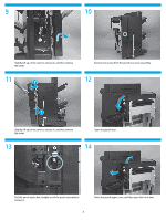
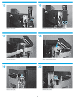
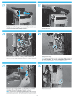
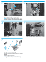
5 Set the punch hole assembly type. Two types of punch hole assemblies are available: the 2/3 6 punch hole assembly (part number A2W94-67901), or the 2/4 punch hole assembly (part number CZ999-67902). Refer to the part number on the replacement part to determine the type of assembly you are installing. Follow the steps below to set the punch hole assembly type. 7 8 2 1 34 5 Turn the product off. ON 1234 Set SW601 to the settings above. Locate the switches and LEDs on the punch controller PCA. • SW601 (callout 1) • LED602 (callout 2) • LED601 (callout 3) • SW602 (callout 4) • SW603 (callout 5) NOTE: SW601 has four electronic switches that can be configure in the ON or OFF position. The punch controller PCA is marked ON and OFF to show the current switch position. 9 Turn the product power on. 8
-
 1
1 -
2
-
 3
3 -
 4
4 -
 5
5 -
 6
6 -
 7
7 -
 8
8 -
 9
9 -
 10
10 -
 11
11 -
 12
12
 |
 |
