HP DL580 ProLiant DL580 Generation 4 Maintenance and Service Guide - Page 30
Removing the front bezel, WARNING, CAUTION, IMPORTANT
 |
UPC - 882780616011
View all HP DL580 manuals
Add to My Manuals
Save this manual to your list of manuals |
Page 30 highlights
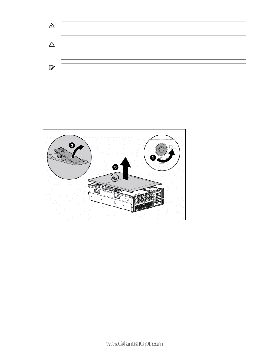
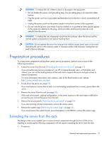
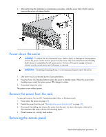
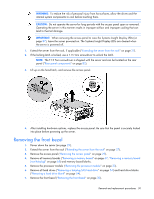
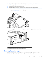
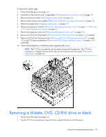
WARNING: To reduce the risk of personal injury from hot surfaces, allow the drives and the internal system components to cool before touching them. CAUTION: Do not operate the server for long periods with the access panel open or removed. Operating the server in this manner results in improper airflow and improper cooling that can lead to thermal damage. IMPORTANT: When removing the access panel to view the Systems Insight Display LEDs (on page 87), leave the server powered on. The Systems Insight Display LEDs are cleared when the server is powered off. 1. Extend the server from the rack, if applicable ("Extending the server from the rack" on page 27). 2. If the locking latch is locked, use a T-15 Torx screwdriver to unlock the latch. NOTE: The T-15 Torx screwdriver is shipped with the server and can be located on the rear panel ("Rear panel components" on page 82). 3. Lift up on the hood latch, and remove the access panel. 4. After installing hardware options, replace the access panel. Be sure that the panel is securely locked into place before powering up the server. Removing the front bezel 1. Power down the server (on page 29). 2. Extend the server from the rack ("Extending the server from the rack" on page 27). 3. Remove the access panel ("Removing the access panel" on page 29). 4. Remove all memory boards ("Removing a memory board" on page 67, "Removing a memory board (non-hot-plug)" on page 65) and memory board blanks. 5. Remove the processor module ("Removing the processor module" on page 33). 6. Remove all hard drives ("Removing a hot-plug SAS hard drive" on page 54) and hard drive blanks ("Removing a hard drive blank" on page 54). 7. Remove the front bezel ("Removing the front bezel" on page 30). Removal and replacement procedures 30
-
 1
1 -
2
-
3
-
4
-
5
-
6
-
7
-
8
-
9
-
10
-
11
-
12
-
13
-
14
-
15
-
16
-
17
-
18
-
19
-
20
-
21
-
22
-
23
-
24
-
 25
25 -
 26
26 -
 27
27 -
 28
28 -
 29
29 -
 30
30 -
 31
31 -
 32
32 -
 33
33 -
 34
34 -
 35
35 -
36
-
37
-
38
-
39
-
40
-
41
-
42
-
43
-
44
-
45
-
46
-
47
-
48
-
49
-
50
-
51
-
52
-
53
-
54
-
55
-
56
-
57
-
58
-
59
-
60
-
61
-
62
-
63
-
64
-
65
-
66
-
67
-
68
-
69
-
70
-
71
-
72
-
73
-
74
-
75
-
76
-
77
-
78
-
79
-
80
-
81
-
82
-
83
-
84
-
85
-
86
-
87
-
88
-
89
-
90
-
91
-
92
-
93
-
94
-
95
-
96
-
97
-
98
-
99
-
100
-
101
-
102
-
103
-
104
-
105
-
106
-
107
-
108
-
109
 |
 |