HP Designjet 510 HP Designjet 510 Printer series - Setup Guide: English (US) - Page 2
Unpack the Main Components, Assemble the Stand - supplies
 |
View all HP Designjet 510 manuals
Add to My Manuals
Save this manual to your list of manuals |
Page 2 highlights
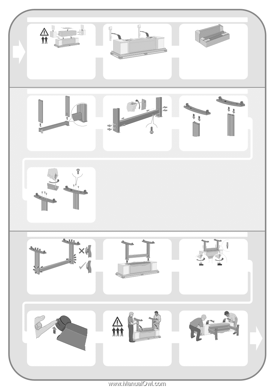
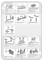
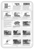
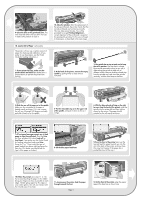
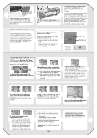
2. Unpack the Main Components 1-Remove: - (E+/A0+-size model) The large box containing the stand and paper bin. Two people may need to do this, as it's rather large. - The two packages containing documentation, cables, etc. - The foam packaging that protects the ends of the printer. 2-Remove: - The foam restraints on top of the printer. - The vertical foam struts at the back of the packaging. 3. Assemble the Stand For assembly of the accessory stand, use the poster supplied with it. 3-For E+/A0+-size models and if you have the stand accessory use the poster supplied with it, open the box that contains the stand and the paper bin-it's the large box above the main printer body. 3-For models without a stand, go to Stage 6: Locate the Front-Panel Overlay and the Pocket Guide on page 4. 1-Attach the legs to the outside of the cross brace. Note that the stand is assembled upside-down. You'll find the screws and screwdriver inside the cross brace. x12 2-Insert twelve screws into the legs. Use the smaller screws with washers. 3-Position the feet on the legs assembly. The wings on the leg brackets pass through the feet. x6 4-Secure the feet to the legs with six screws. Again, use the smaller screws with washers. 4. Attach the Stand to the printer For assembly of the accessory stand, use the poster supplied with it x4 1-Check that all the stand screws are tight. If you can't tighten all the screws properly, try unscrewing one or two so that the legs, feet and cross braces are properly aligned, and then retighten them. 2-Put the stand assembly onto the printer. Peel open the protective cover and then place the stand onto the printer. 3-Secure the stand with the four screws that have large flat heads. Two screws (on one leg) are secured normally. CAUTION: Two of the screws on the same leg will appear to be not fully tightened, as they will not go in as far as the others-they should be firm but not over tight. 4-Ensure all four brakes are applied, as shown. 5-Tilt and lift the printer (1): WARNING: 2-3 people for the E+/A0+-size model; 2 people for the D/A1-size model. CAUTION: Ensure the area in front of the printer is clear of any obstacles such as packaging or rolls of paper. Page 2 6-Tilt and lift the printer (2): Tilt the printer through 90-degrees onto its side, and then stand it up on its legs. The printer may seem a little wobbly on one side, but that is correct provided the screws have been tightened as indicated in previous steps.
-
 1
1 -
 2
2 -
 3
3 -
 4
4 -
 5
5 -
 6
6 -
 7
7 -
 8
8
 |
 |