HP ENVY 13-ab000 Envy Notebook PC model numbers 13-ab001 through 13-ab099; CTO - Page 56
Disconnect the following cables from the system board, Power connector cable
 |
View all HP ENVY 13-ab000 manuals
Add to My Manuals
Save this manual to your list of manuals |
Page 56 highlights
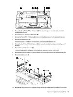
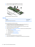
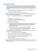
Description Equipped with an Intel Core i3-7100U 2.40-GHz processor (2133-MHz FSB, 3.0-MB L3 cache, dual core, 15 W), 4-GB of system memory, and the Windows 10 Professional operating system Equipped with an Intel Core i3-7100U 2.40-GHz processor (2133-MHz FSB, 3.0-MB L3 cache, dual core, 15 W), 4-GB of system memory, and a non-Windows operating system Spare part number 909250-601 909250-001 Before removing the system board, follow these steps: 1. Turn off the computer. If you are unsure whether the computer is off or in Hibernation, turn the computer on, and then shut it down through the operating system. 2. Disconnect the power from the computer by unplugging the power cord from the computer. 3. Disconnect all external devices from the computer. 4. Remove the bottom cover (see Bottom cover on page 27), and then remove the following components: a. Battery (see Battery on page 29) b. Solid-state drive (see Solid-state drive on page 33) c. Left and right fans (see Fans on page 34) NOTE: When replacing the system board, be sure that the WLAN module (see WLAN module on page 31) and the heat sink (see Heat sink on page 50) are removed from the defective system board and installed on the replacement system board: Remove the system board: 1. Disconnect the following cables from the system board: (1) Power connector cable (2) WLAN module antenna cables NOTE: The WLAN "Main/#1"antenna cable is connected to the WLAN module "Main" terminal. The WLAN "Aux/#2"antenna cable is connected to the WLAN module "Aux" terminal. (6) Display panel ZIF connector cable (7) Webcam/microphone module cable (3) Keyboard ZIF connector cable (4) Backlight ZIF connector cable (5) TouchPad board ZIF connector cable (8) Speaker cable (9) RTC battery cable 48 Chapter 5 Removal and replacement procedures
-
 1
1 -
2
-
3
-
4
-
5
-
6
-
7
-
8
-
9
-
10
-
11
-
12
-
13
-
14
-
15
-
16
-
17
-
18
-
19
-
20
-
21
-
22
-
23
-
24
-
25
-
26
-
27
-
28
-
29
-
30
-
31
-
32
-
33
-
34
-
35
-
36
-
37
-
38
-
39
-
40
-
41
-
42
-
43
-
44
-
45
-
46
-
47
-
48
-
49
-
50
-
 51
51 -
 52
52 -
 53
53 -
 54
54 -
 55
55 -
 56
56 -
 57
57 -
 58
58 -
 59
59 -
 60
60 -
 61
61 -
62
-
63
-
64
-
65
-
66
-
67
-
68
-
69
-
70
-
71
-
72
-
73
-
74
-
75
-
76
-
77
 |
 |
