HP ENVY 13-ab000 Envy Notebook PC model numbers 13-ab001 through 13-ab099; CTO - Page 57
Remove the two Phillips PM2.5×4.1 screws, top cover.
 |
View all HP ENVY 13-ab000 manuals
Add to My Manuals
Save this manual to your list of manuals |
Page 57 highlights
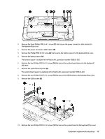
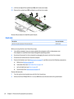
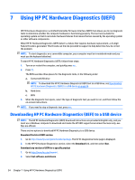
2. Remove the three Phillips PM2.5×4.1 screws (1) that secure the power connector cable bracket to the keyboard/top cover. 3. Remove the power connector cable bracket (2). 4. Remove the Phillips PM2.0×3.2 screw (3) that secures the battery spacer to the keyboard/top cover. 5. Remove the battery spacer (4). The battery spacer is included in the Plastics Kit, spare part number 909633-001. 6. Remove the two Phillips PM2.0×3.2 screws (5) that secure the system board spacer to the keyboard/ top cover. 7. Remove the system board spacer (6). The system board spacer is available in the Plastics Kit, spare part number 909633-001. 8. Remove the two Phillips PM2.5×4.1 screws (7) that secure the USB bracket to the keyboard/top cover. 9. Remove the USB bracket (8). 10. Remove the two Phillips PM2.0×3.2 screws (1) that secure the system board to the keyboard/top cover. Component replacement procedures 49
-
 1
1 -
2
-
3
-
4
-
5
-
6
-
7
-
8
-
9
-
10
-
11
-
12
-
13
-
14
-
15
-
16
-
17
-
18
-
19
-
20
-
21
-
22
-
23
-
24
-
25
-
26
-
27
-
28
-
29
-
30
-
31
-
32
-
33
-
34
-
35
-
36
-
37
-
38
-
39
-
40
-
41
-
42
-
43
-
44
-
45
-
46
-
47
-
48
-
49
-
50
-
51
-
 52
52 -
 53
53 -
 54
54 -
 55
55 -
 56
56 -
 57
57 -
 58
58 -
 59
59 -
 60
60 -
 61
61 -
 62
62 -
63
-
64
-
65
-
66
-
67
-
68
-
69
-
70
-
71
-
72
-
73
-
74
-
75
-
76
-
77
 |
 |
