HP ENVY 13-ay0000 Maintenance and Service Guide - Page 66
System board, the defective system board and installed on the replacement system board
 |
View all HP ENVY 13-ay0000 manuals
Add to My Manuals
Save this manual to your list of manuals |
Page 66 highlights
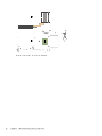
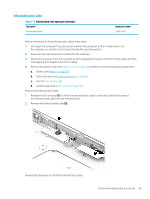
System board NOTE: The system board spare part kit includes the processor, a graphics subsystem with UMA memory, onboard system memory, replacement thermal material, and the Windows 10 operating system. Table 5-10 System board spare part information Description Spare part number Equipped with an AMD Ryzen7 4700U processor and 16 GB of system memory Equipped with an AMD Ryzen7 4700U processor and 8 GB of system memory Equipped with an AMD Ryzen5 4500U processor and 8 GB of system memory Equipped with an AMD Ryzen3 4300U processor and 8 GB of system memory L94491-601 L94492-601 L94490-601 L94489-601 Before removing the system board, follow these steps: 1. Shut down the computer. If you are unsure whether the computer is off or in Hibernation, turn the computer on, and then shut it down through the operating system. 2. Disconnect all external devices connected to the computer. 3. Disconnect the power from the computer by first unplugging the power cord from the AC outlet, and then unplugging the AC adapter from the computer. 4. Remove the bottom cover (see Bottom cover on page 30), and then remove the following components: a. Battery (see Battery on page 33) b. Solid-state drive (see Solid-state drive on page 35) c. Fan (see Fan on page 38) NOTE: When replacing the system board, make sure the following components are removed from the defective system board and installed on the replacement system board: ● WLAN module (see WLAN module on page 34) ● Solid-state drive (see Solid-state drive on page 35) ● Heat sink (see Heat sink on page 61) Remove the system board: 1. Remove the cover (1) that secures the WLAN antenna cables to the WLAN module. 58 Chapter 5 Removal and replacement procedures
-
 1
1 -
2
-
3
-
4
-
5
-
6
-
7
-
8
-
9
-
10
-
11
-
12
-
13
-
14
-
15
-
16
-
17
-
18
-
19
-
20
-
21
-
22
-
23
-
24
-
25
-
26
-
27
-
28
-
29
-
30
-
31
-
32
-
33
-
34
-
35
-
36
-
37
-
38
-
39
-
40
-
41
-
42
-
43
-
44
-
45
-
46
-
47
-
48
-
49
-
50
-
51
-
52
-
53
-
54
-
55
-
56
-
57
-
58
-
59
-
60
-
 61
61 -
 62
62 -
 63
63 -
 64
64 -
 65
65 -
 66
66 -
 67
67 -
 68
68 -
 69
69 -
 70
70 -
 71
71 -
72
-
73
-
74
-
75
-
76
-
77
-
78
-
79
-
80
-
81
-
82
-
83
-
84
-
85
-
86
-
87
-
88
-
89
-
90
-
91
-
92
-
93
 |
 |
