HP ENVY 13-ay0000 Maintenance and Service Guide - Page 68
Remove the Phillips M2.0×3.0 screw, by sliding it up and to the right at an angle.
 |
View all HP ENVY 13-ay0000 manuals
Add to My Manuals
Save this manual to your list of manuals |
Page 68 highlights
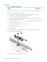
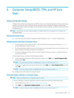
4. Remove the Phillips M2.0×3.0 screw (2) that secures the system board and the I/O bracket (3) to the keyboard/top cover. 5. Lift the left side the system board (1) until it rests at an angle. 6. Remove the system board (2) by sliding it up and to the right at an angle. Reverse this procedure to install the system board. 60 Chapter 5 Removal and replacement procedures
-
 1
1 -
2
-
3
-
4
-
5
-
6
-
7
-
8
-
9
-
10
-
11
-
12
-
13
-
14
-
15
-
16
-
17
-
18
-
19
-
20
-
21
-
22
-
23
-
24
-
25
-
26
-
27
-
28
-
29
-
30
-
31
-
32
-
33
-
34
-
35
-
36
-
37
-
38
-
39
-
40
-
41
-
42
-
43
-
44
-
45
-
46
-
47
-
48
-
49
-
50
-
51
-
52
-
53
-
54
-
55
-
56
-
57
-
58
-
59
-
60
-
61
-
62
-
 63
63 -
 64
64 -
 65
65 -
 66
66 -
 67
67 -
 68
68 -
 69
69 -
 70
70 -
 71
71 -
 72
72 -
 73
73 -
74
-
75
-
76
-
77
-
78
-
79
-
80
-
81
-
82
-
83
-
84
-
85
-
86
-
87
-
88
-
89
-
90
-
91
-
92
-
93
 |
 |

4.
Remove the Phillips M2.0×3.0 screw
(2)
that secures the system board and the I/O bracket
(3)
to
the keyboard/top cover.
5.
Lift the left side the system board
(1)
until it rests at an angle.
6.
Remove the system board
(2)
by sliding it up and to the right at an angle.
Reverse this procedure to install the system board.
60
Chapter 5
Removal and replacement procedures