HP ENVY 15-ae100 ENVY Notebook PC Maintenance and Service Guide - Page 66
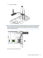
Note the way the speaker cable is routed near the RTC battery, performance of the speakers.
 |
View all HP ENVY 15-ae100 manuals
Add to My Manuals
Save this manual to your list of manuals |
Page 66 highlights
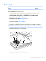
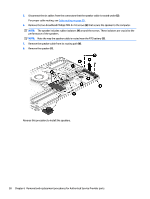
5. Disconnect the six cables from the connectors that the speaker cable is routed under (2). For proper cable routing, see Cable routing on page 59 . 6. Remove the two broadhead Phillips PM2.0×2.0 screws (3) that secure the speaker to the computer. NOTE: The speaker includes rubber isolators (4) around the screws. These isolators are crucial to the performance of the speakers. NOTE: Note the way the speaker cable is routed near the RTC battery (5). 7. Remove the speaker cable from its routing path (6). 8. Remove the speaker (7). Reverse this procedure to install the speakers. 58 Chapter 6 Removal and replacement procedures for Authorized Service Provider parts
-
 1
1 -
2
-
3
-
4
-
5
-
6
-
7
-
8
-
9
-
10
-
11
-
12
-
13
-
14
-
15
-
16
-
17
-
18
-
19
-
20
-
21
-
22
-
23
-
24
-
25
-
26
-
27
-
28
-
29
-
30
-
31
-
32
-
33
-
34
-
35
-
36
-
37
-
38
-
39
-
40
-
41
-
42
-
43
-
44
-
45
-
46
-
47
-
48
-
49
-
50
-
51
-
52
-
53
-
54
-
55
-
56
-
57
-
58
-
59
-
60
-
 61
61 -
 62
62 -
 63
63 -
 64
64 -
 65
65 -
 66
66 -
 67
67 -
 68
68 -
 69
69 -
 70
70 -
 71
71 -
72
-
73
-
74
-
75
-
76
-
77
-
78
-
79
-
80
-
81
-
82
-
83
-
84
-
85
-
86
-
87
-
88
-
89
-
90
-
91
-
92
-
93
-
94
-
95
-
96
-
97
-
98
-
99
-
100
-
101
-
102
-
103
-
104
-
105
-
106
-
107
-
108
-
109
-
110
-
111
-
112
-
113
-
114
-
115
-
116
-
117
-
118
-
119
-
120
-
121
-
122
-
123
-
124
-
125
-
126
-
127
 |
 |

5.
Disconnect the six cables from the connectors that the speaker cable is routed under
(2)
.
For proper cable routing, see
Cable routing
on page
59
.
6.
Remove the two broadhead Phillips PM2.0×2.0 screws
(3)
that secure the speaker to the computer.
NOTE:
The speaker includes rubber isolators
(4)
around the screws. These isolators are crucial to the
performance of the speakers.
NOTE:
Note the way the speaker cable is routed near the RTC battery
(5)
.
7.
Remove the speaker cable from its routing path
(6)
.
8.
Remove the speaker
(7)
.
Reverse this procedure to install the speakers.
58
Chapter 6
Removal and replacement procedures for Authorized Service Provider parts