HP ENVY 15-ae100 ENVY Notebook PC Maintenance and Service Guide - Page 85
the left and right edges, Flex the inside of the top edge
 |
View all HP ENVY 15-ae100 manuals
Add to My Manuals
Save this manual to your list of manuals |
Page 85 highlights
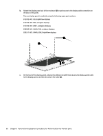
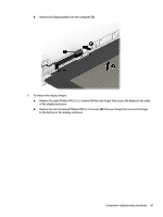
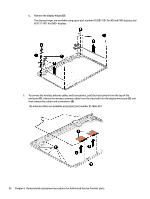
a. Remove the two screw covers (1) and two Phillips PM2.0×3.0 screws (2) that secure the bezel to the display. b. Flex the inside of the top edge (3), the left and right edges (4), and the bottom edge (5) of the display bezel until the bezel disengages from the display enclosure. c. Remove the display bezel (6). The bezel is available using spare part number 812674-001. Component replacement procedures 77
-
 1
1 -
2
-
3
-
4
-
5
-
6
-
7
-
8
-
9
-
10
-
11
-
12
-
13
-
14
-
15
-
16
-
17
-
18
-
19
-
20
-
21
-
22
-
23
-
24
-
25
-
26
-
27
-
28
-
29
-
30
-
31
-
32
-
33
-
34
-
35
-
36
-
37
-
38
-
39
-
40
-
41
-
42
-
43
-
44
-
45
-
46
-
47
-
48
-
49
-
50
-
51
-
52
-
53
-
54
-
55
-
56
-
57
-
58
-
59
-
60
-
61
-
62
-
63
-
64
-
65
-
66
-
67
-
68
-
69
-
70
-
71
-
72
-
73
-
74
-
75
-
76
-
77
-
78
-
79
-
 80
80 -
 81
81 -
 82
82 -
 83
83 -
 84
84 -
 85
85 -
 86
86 -
 87
87 -
 88
88 -
 89
89 -
 90
90 -
91
-
92
-
93
-
94
-
95
-
96
-
97
-
98
-
99
-
100
-
101
-
102
-
103
-
104
-
105
-
106
-
107
-
108
-
109
-
110
-
111
-
112
-
113
-
114
-
115
-
116
-
117
-
118
-
119
-
120
-
121
-
122
-
123
-
124
-
125
-
126
-
127
 |
 |

a.
Remove the two screw covers
(1)
and two Phillips PM2.0×3.0 screws
(2)
that secure the bezel to
the display.
b.
Flex the inside of the top edge
(3)
, the left and right edges
(4)
, and the bottom edge
(5)
of the
display bezel until the bezel disengages from the display enclosure.
c.
Remove the display bezel
(6)
.
The bezel is available using spare part number 812674-001.
Component replacement procedures
77