HP ENVY 15-k000 HP ENVY 17 Notebook PC HP ENVY 15 Notebook PC - Maintenance an - Page 59
Carefully disconnect the following cables, Use a thin, non-conductive tool to lift the top cover..
 |
View all HP ENVY 15-k000 manuals
Add to My Manuals
Save this manual to your list of manuals |
Page 59 highlights
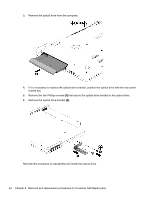
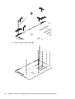
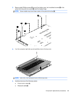
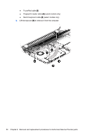
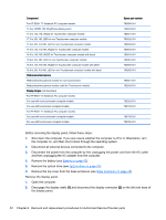
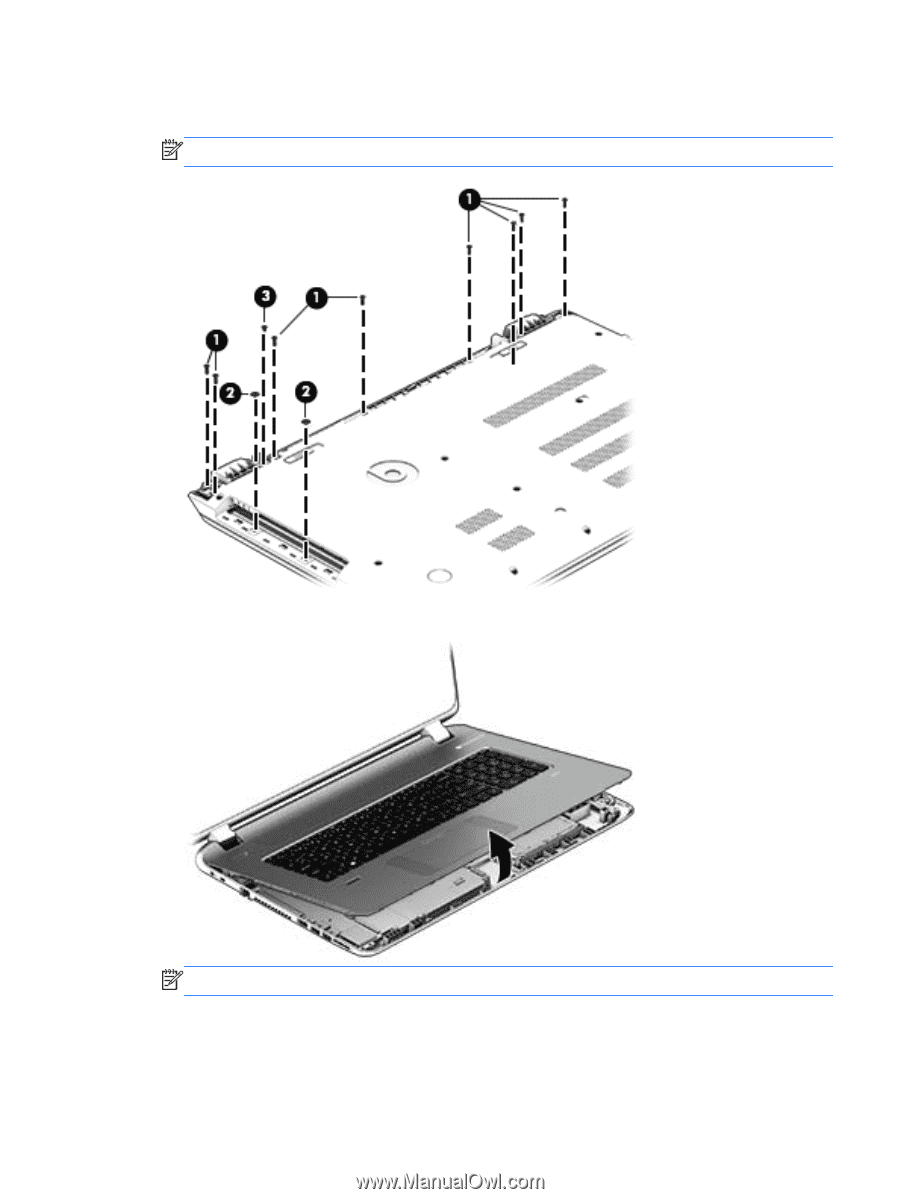
3. Remove eight Phillips screws (1) around the battery area, two broadhead screws (2) in the optical drive bay and one screw (3) near the display hinge. NOTE: Some models may have three screws in the optical drive bay (2). 4. Turn the computer right side up and carefully remove the top cover. NOTE: Use a thin, non-conductive tool to lift the top cover.. 5. Carefully disconnect the following cables: ● Power button cable (1) ● Keyboard cable (2) Component replacement procedures 49
-
 1
1 -
2
-
3
-
4
-
5
-
6
-
7
-
8
-
9
-
10
-
11
-
12
-
13
-
14
-
15
-
16
-
17
-
18
-
19
-
20
-
21
-
22
-
23
-
24
-
25
-
26
-
27
-
28
-
29
-
30
-
31
-
32
-
33
-
34
-
35
-
36
-
37
-
38
-
39
-
40
-
41
-
42
-
43
-
44
-
45
-
46
-
47
-
48
-
49
-
50
-
51
-
52
-
53
-
 54
54 -
 55
55 -
 56
56 -
 57
57 -
 58
58 -
 59
59 -
 60
60 -
 61
61 -
 62
62 -
 63
63 -
 64
64 -
65
-
66
-
67
-
68
-
69
-
70
-
71
-
72
-
73
-
74
-
75
-
76
-
77
-
78
-
79
-
80
-
81
-
82
-
83
-
84
-
85
-
86
-
87
-
88
-
89
-
90
-
91
-
92
-
93
-
94
-
95
-
96
-
97
-
98
-
99
-
100
-
101
-
102
-
103
-
104
-
105
-
106
-
107
-
108
-
109
-
110
-
111
-
112
-
113
-
114
-
115
-
116
-
117
-
118
 |
 |
3.
Remove eight Phillips screws
(1)
around the battery area, two broadhead screws
(2)
in the
optical drive bay and one screw
(3)
near the display hinge.
NOTE:
Some models may have three screws in the optical drive bay
(2)
.
4.
Turn the computer right side up and carefully remove the top cover.
NOTE:
Use a thin, non-conductive tool to lift the top cover..
5.
Carefully disconnect the following cables:
●
Power button cable
(1)
●
Keyboard cable
(2)
Component replacement procedures
49