HP ENVY 15-k000 HP ENVY 17 Notebook PC HP ENVY 15 Notebook PC - Maintenance an - Page 88
Heat sink, Remove the WLAN module see
 |
View all HP ENVY 15-k000 manuals
Add to My Manuals
Save this manual to your list of manuals |
Page 88 highlights
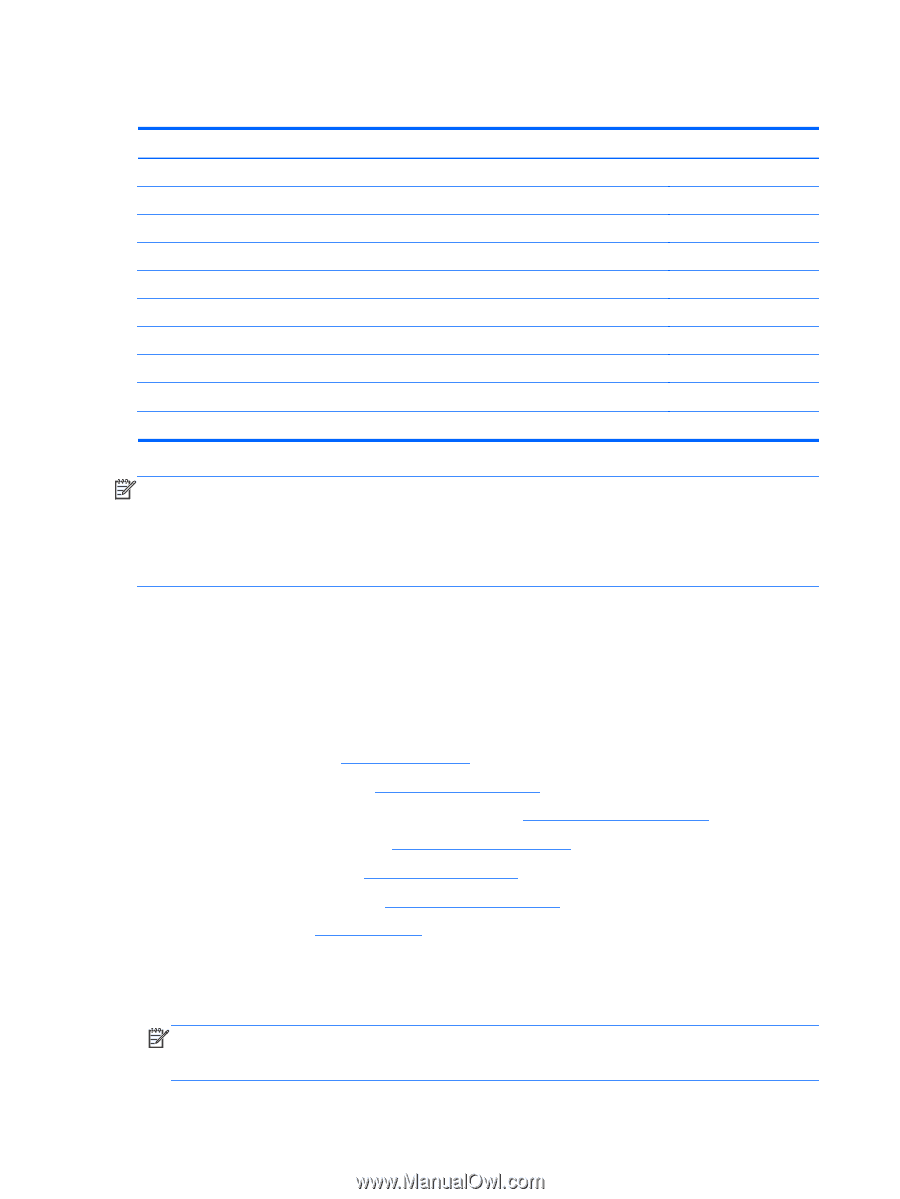
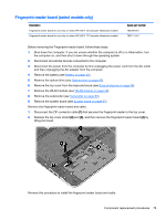
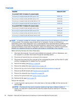
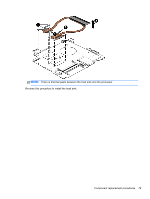
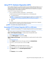
Heat sink Description For use with HP ENVY 15 Notebook PC computer models: For use only on computer models with UMA memory 19 W For use only on computer models with UMA memory 47 W For use only on computer models with discrete memory 19 W For use only on computer models with discrete memory 35 W For use with HP ENVY 17 Notebook PC computer models: For use only on computer models with UMA memory 19 W For use only on computer models with UMA memory 47 W For use only on computer models with discrete memory 19 W For use only on computer models with discrete memory 35 W Spare part number 763701-001 763702-001 763703-001 763704-001 763701-001 763702-001 763703-001 763704-001 NOTE: To properly ventilate the computer, allow at least 7.6 cm (3 in) of clearance on the left side of the computer. The computer uses an electric fan for ventilation. The fan is controlled by a temperature sensor and is designed to turn on automatically when high temperature conditions exist. These conditions are affected by high external temperatures, system power consumption, power management/battery conservation configurations, battery fast charging, and software requirements. Exhaust air is displaced through the ventilation grill located on the left side of the computer. Before removing the heat sink, follow these steps: 1. Shut down the computer. If you are unsure whether the computer is off or in Hibernation, turn the computer on, and then shut it down through the operating system. 2. Disconnect all external devices connected to the computer. 3. Disconnect the power from the computer by first unplugging the power cord from the AC outlet and then unplugging the AC adapter from the computer. 4. Remove the battery (see Battery on page 42), 5. Remove the optical drive (see Optical drive on page 43). 6. Remove the top cover from the base enclosure (see Base enclosure on page 46). 7. Remove the WLAN module (see WLAN module on page 59). 8. Remove the subwoofer (see Subwoofer on page 63). 9. Remove the system board (see System board on page 67). 10. Remove the fan (see Fan on page 77). Remove the heat sink: ▲ Loosen the seven captive screws in the order listed on the heat sink (1), and then remove the heat sink (2). NOTE: The heat sink may vary by computer model and may have a different number of screws. The heat sink is marked with the order the screws should be removed in. Follow the order shown. 78 Chapter 6 Removal and replacement procedures for Authorized Service Provider parts
-
 1
1 -
2
-
3
-
4
-
5
-
6
-
7
-
8
-
9
-
10
-
11
-
12
-
13
-
14
-
15
-
16
-
17
-
18
-
19
-
20
-
21
-
22
-
23
-
24
-
25
-
26
-
27
-
28
-
29
-
30
-
31
-
32
-
33
-
34
-
35
-
36
-
37
-
38
-
39
-
40
-
41
-
42
-
43
-
44
-
45
-
46
-
47
-
48
-
49
-
50
-
51
-
52
-
53
-
54
-
55
-
56
-
57
-
58
-
59
-
60
-
61
-
62
-
63
-
64
-
65
-
66
-
67
-
68
-
69
-
70
-
71
-
72
-
73
-
74
-
75
-
76
-
77
-
78
-
79
-
80
-
81
-
82
-
 83
83 -
 84
84 -
 85
85 -
 86
86 -
 87
87 -
 88
88 -
 89
89 -
 90
90 -
 91
91 -
 92
92 -
 93
93 -
94
-
95
-
96
-
97
-
98
-
99
-
100
-
101
-
102
-
103
-
104
-
105
-
106
-
107
-
108
-
109
-
110
-
111
-
112
-
113
-
114
-
115
-
116
-
117
-
118
 |
 |