HP ENVY 15-k000 HP ENVY 17 Notebook PC HP ENVY 15 Notebook PC - Maintenance an - Page 69
WLAN module
 |
View all HP ENVY 15-k000 manuals
Add to My Manuals
Save this manual to your list of manuals |
Page 69 highlights
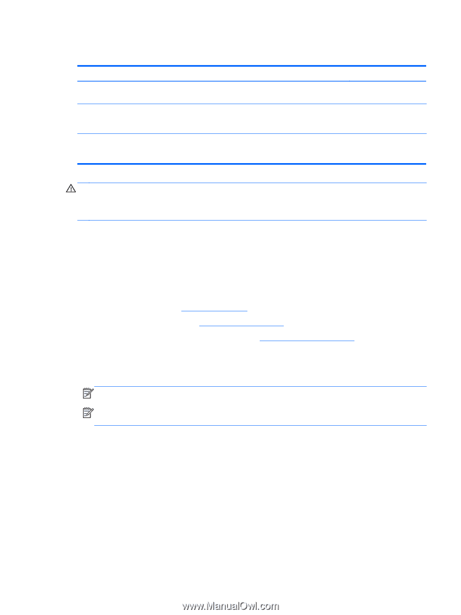
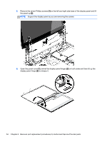
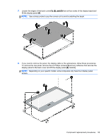
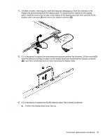
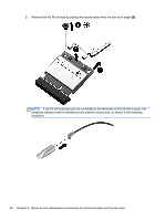
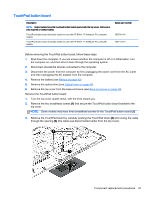
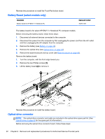
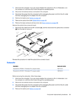
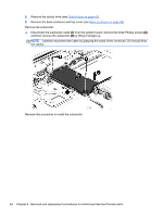
WLAN module Description Spare part number Intel Dual Band Wireless-AC 3160 802.11 ac 1x1 WiFi + BT 4.0 combo adapter for use only with 710662-005 HP ENVY 17 Notebook PC computer models or HP ENVY 15 Notebook PC computer models Qualcomm Atheros AR9485 802.11 bgn 1x1 Wi-Fi adapter for use only with HP ENVY 17 Notebook PC computer models or HP ENVY 15 Notebook PC computer models available for Windows 8.1 and Windows 7 675794-005 Intel Dual Band Wireless-AC 7260 802.11 ac 2x2 WiFi + BT 4.0 Combo Adapter non-Vpro version w/ dual antennas for use with HP ENVY 17 Notebook PC computer models only for Windows 8.1 and Windows 7 756753-005 CAUTION: To prevent an unresponsive system, replace the wireless module only with a wireless module authorized for use in the computer by the governmental agency that regulates wireless devices in your country or region. If you replace the module and then receive a warning message, remove the module to restore device functionality, and then contact technical support. Before removing the WLAN module, follow these steps: 1. Shut down the computer. If you are unsure whether the computer is off or in Hibernation, turn the computer on, and then shut it down through the operating system. 2. Disconnect all external devices connected to the computer. 3. Disconnect the power from the computer by first unplugging the power cord from the AC outlet and then unplugging the AC adapter from the computer. 4. Remove the battery (see Battery on page 42). 5. Remove the optical drive (see Optical drive on page 43). 6. Remove the base enclosure and top cover (see Base enclosure on page 46). Remove the WLAN module: 1. Disconnect the #1 and #2 WLAN antenna cables from the WLAN module (1) if you have not already done so to remove the display panel.. NOTE: The WLAN module may have two screws depending on the model. NOTE: The #1 WLAN antenna cable is connected to the WLAN module #1 main terminal. The #2 WLAN antenna cable is connected to the WLAN module #2 auxiliary terminal. 2. Remove the Phillips screw(s) (2) that secure the WLAN module to the system board. (The WLAN module tilts up.) Component replacement procedures 59
-
 1
1 -
2
-
3
-
4
-
5
-
6
-
7
-
8
-
9
-
10
-
11
-
12
-
13
-
14
-
15
-
16
-
17
-
18
-
19
-
20
-
21
-
22
-
23
-
24
-
25
-
26
-
27
-
28
-
29
-
30
-
31
-
32
-
33
-
34
-
35
-
36
-
37
-
38
-
39
-
40
-
41
-
42
-
43
-
44
-
45
-
46
-
47
-
48
-
49
-
50
-
51
-
52
-
53
-
54
-
55
-
56
-
57
-
58
-
59
-
60
-
61
-
62
-
63
-
 64
64 -
 65
65 -
 66
66 -
 67
67 -
 68
68 -
 69
69 -
 70
70 -
 71
71 -
 72
72 -
 73
73 -
 74
74 -
75
-
76
-
77
-
78
-
79
-
80
-
81
-
82
-
83
-
84
-
85
-
86
-
87
-
88
-
89
-
90
-
91
-
92
-
93
-
94
-
95
-
96
-
97
-
98
-
99
-
100
-
101
-
102
-
103
-
104
-
105
-
106
-
107
-
108
-
109
-
110
-
111
-
112
-
113
-
114
-
115
-
116
-
117
-
118
 |
 |