HP ENVY 15-k000 HP ENVY 17 Notebook PC HP ENVY 15 Notebook PC - Maintenance an - Page 63
the display panel removal., The power connector cover has two screws, however
 |
View all HP ENVY 15-k000 manuals
Add to My Manuals
Save this manual to your list of manuals |
Page 63 highlights
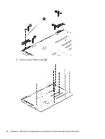
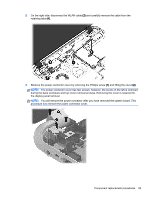
3. On the right side, disconnect the WLAN cable (3) and carefully remove the cable from the retaining tabs (4). 4. Remove the power connector cover by removing the Phillips screw (1) and lifting the cover (2). NOTE: The power connector cover has two screws, however, the screw on the left is removed during the base enclosure and top cover removal process. Removing the cover is required for the display panel removal. NOTE: You will remove the power connector after you have removed the system board. This procedure is to remove the power connector cover. Component replacement procedures 53
-
 1
1 -
2
-
3
-
4
-
5
-
6
-
7
-
8
-
9
-
10
-
11
-
12
-
13
-
14
-
15
-
16
-
17
-
18
-
19
-
20
-
21
-
22
-
23
-
24
-
25
-
26
-
27
-
28
-
29
-
30
-
31
-
32
-
33
-
34
-
35
-
36
-
37
-
38
-
39
-
40
-
41
-
42
-
43
-
44
-
45
-
46
-
47
-
48
-
49
-
50
-
51
-
52
-
53
-
54
-
55
-
56
-
57
-
 58
58 -
 59
59 -
 60
60 -
 61
61 -
 62
62 -
 63
63 -
 64
64 -
 65
65 -
 66
66 -
 67
67 -
 68
68 -
69
-
70
-
71
-
72
-
73
-
74
-
75
-
76
-
77
-
78
-
79
-
80
-
81
-
82
-
83
-
84
-
85
-
86
-
87
-
88
-
89
-
90
-
91
-
92
-
93
-
94
-
95
-
96
-
97
-
98
-
99
-
100
-
101
-
102
-
103
-
104
-
105
-
106
-
107
-
108
-
109
-
110
-
111
-
112
-
113
-
114
-
115
-
116
-
117
-
118
 |
 |
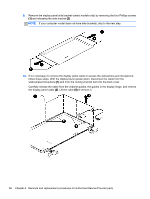
3.
On the right side, disconnect the WLAN cable
(3)
and carefully remove the cable from the
retaining tabs
(4)
.
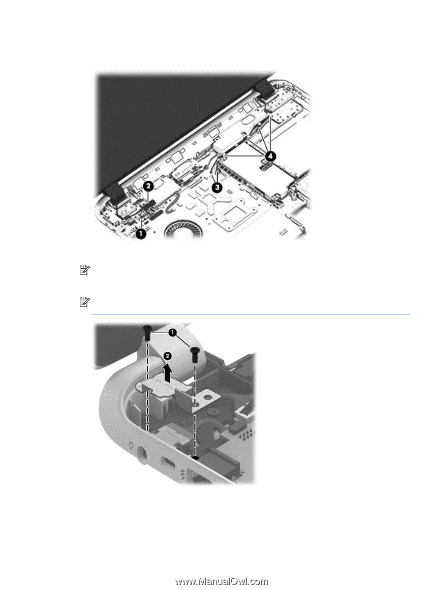
4.
Remove the power connector cover by removing the Phillips screw
(1)
and lifting the cover
(2)
.
NOTE:
The power connector cover has two screws, however, the screw on the left is removed
during the base enclosure and top cover removal process. Removing the cover is required for
the display panel removal.
NOTE:
You will remove the power connector after you have removed the system board. This
procedure is to remove the power connector cover.
Component replacement procedures
53