HP ENVY 15-w000 Maintenance and Service Guide - Page 54
Heat sink
 |
View all HP ENVY 15-w000 manuals
Add to My Manuals
Save this manual to your list of manuals |
Page 54 highlights
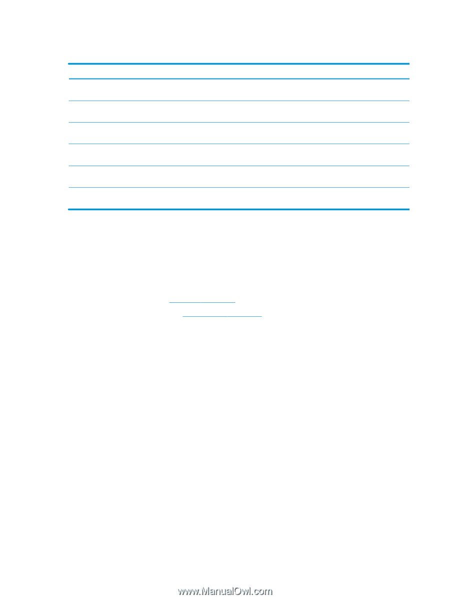
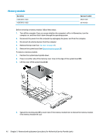
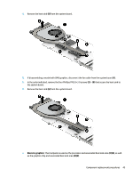
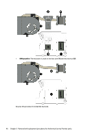
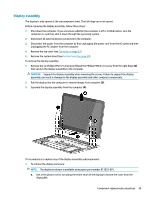
Heat sink Description Spare part number Heat sink for use in models with 5th generation Intel processors and discrete graphics memory (includes 807524-001 replacement thermal material) Heat sink for use in models with 5th generation Intel processors and UMA graphics memory (includes replacement thermal material) 807523-001 Heat sink for use in models with 6th generation Intel processors and discrete graphics memory (includes 828732-001 replacement thermal material) Heat sink for use in models with 6th generation Intel processors and UMA graphics memory (includes replacement thermal material) 828733-001 Heat sink for use in models with 7th generation Intel processors and discrete graphics memory (includes 860899-001 replacement thermal material) Heat sink for use in models with 7th generation Intel processors and UMA graphics memory (includes replacement thermal material) 860900-001 Before removing the heat sink, follow these steps: 1. Turn off the computer. If you are unsure whether the computer is off or in Hibernation, turn the computer on, and then shut it down through the operating system. 2. Disconnect the power from the computer by unplugging the power cord from the computer. 3. Disconnect all external devices from the computer. 4. Remove the top cover (see Top cover on page 27). 5. Remove the system board (see System board on page 39). To remove the heat sink assembly: 1. Position the system board upside down. 2. If disassembling a model with discrete graphics, disconnect the fan cable from the system board (1). 3. In the order indicated, loosen the six Phillips screws (2) - (7) that secure the heat sink to the system board. 44 Chapter 5 Removal and replacement procedures for Authorized Service Provider parts
-
 1
1 -
2
-
3
-
4
-
5
-
6
-
7
-
8
-
9
-
10
-
11
-
12
-
13
-
14
-
15
-
16
-
17
-
18
-
19
-
20
-
21
-
22
-
23
-
24
-
25
-
26
-
27
-
28
-
29
-
30
-
31
-
32
-
33
-
34
-
35
-
36
-
37
-
38
-
39
-
40
-
41
-
42
-
43
-
44
-
45
-
46
-
47
-
48
-
 49
49 -
 50
50 -
 51
51 -
 52
52 -
 53
53 -
 54
54 -
 55
55 -
 56
56 -
 57
57 -
 58
58 -
 59
59 -
60
-
61
-
62
-
63
-
64
-
65
-
66
-
67
-
68
-
69
-
70
-
71
-
72
-
73
-
74
-
75
-
76
-
77
-
78
-
79
-
80
-
81
-
82
-
83
-
84
-
85
-
86
-
87
-
88
-
89
-
90
-
91
-
92
-
93
-
94
-
95
-
96
 |
 |