HP ENVY 17-2090nr HP ENVY 17 (model numbers 2000 through 2099) - Maintenance a - Page 83
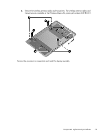
that secure the hinge covers to the display, Remove the two Phillips PM2.0×4.0 screws
 |
View all HP ENVY 17-2090nr manuals
Add to My Manuals
Save this manual to your list of manuals |
Page 83 highlights
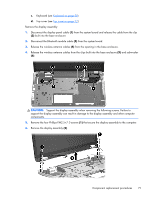
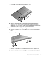
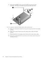
c. Disconnect the display panel cable (3) from the display panel. d. Remove the display panel cable. The display panel cable is available using spare part numbers 642123-001 (for use only with computer models equipped with a 2D display assembly) and 621337-001 (for use only with computer models equipped with a 3D display assembly), and includes the webcam cable and Bluetooth module cable. 11. If it is necessary to replace the display hinges and hinge covers: a. Remove the two Phillips PM2.0×4.0 screws (1) that secure the hinge covers to the display bezel. b. Remove the hinge covers (2). c. Remove the six Phillips PM2.5×5.0 screws (1) that secure the hinges to the display panel. d. Remove the four Phillips PM2.0×4.0 screws (2) that secure the hinges to the display panel. Component replacement procedures 75
-
 1
1 -
2
-
3
-
4
-
5
-
6
-
7
-
8
-
9
-
10
-
11
-
12
-
13
-
14
-
15
-
16
-
17
-
18
-
19
-
20
-
21
-
22
-
23
-
24
-
25
-
26
-
27
-
28
-
29
-
30
-
31
-
32
-
33
-
34
-
35
-
36
-
37
-
38
-
39
-
40
-
41
-
42
-
43
-
44
-
45
-
46
-
47
-
48
-
49
-
50
-
51
-
52
-
53
-
54
-
55
-
56
-
57
-
58
-
59
-
60
-
61
-
62
-
63
-
64
-
65
-
66
-
67
-
68
-
69
-
70
-
71
-
72
-
73
-
74
-
75
-
76
-
77
-
 78
78 -
 79
79 -
 80
80 -
 81
81 -
 82
82 -
 83
83 -
 84
84 -
 85
85 -
 86
86 -
 87
87 -
 88
88 -
89
-
90
-
91
-
92
-
93
-
94
-
95
-
96
-
97
-
98
-
99
-
100
-
101
-
102
-
103
-
104
-
105
-
106
-
107
-
108
-
109
-
110
-
111
-
112
-
113
-
114
-
115
-
116
-
117
-
118
 |
 |
