HP ENVY 17-2090nr HP ENVY 17 (model numbers 2000 through 2099) - Maintenance a - Page 84
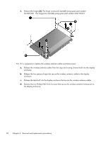
Release the two pieces of tape that secure the wireless antenna cables to the display
 |
View all HP ENVY 17-2090nr manuals
Add to My Manuals
Save this manual to your list of manuals |
Page 84 highlights
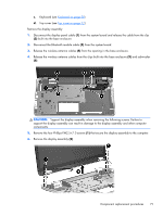
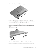
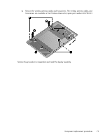
e. Remove the hinges (3). The hinge covers are available using spare part number 604063-001. The hinges are available using spare part number 603778-001. 12. If it is necessary to replace the wireless antenna cables and transceivers: a. Release the wireless antenna cables from the clips and routing channel built into the display enclosure. b. Release the two pieces of tape that secure the wireless antenna cables to the display enclosure. c. Release the tabs built into the display enclosure that secure the wireless antenna cables. d. Remove the two Phillips PM2.0×4.0 screws that secure the wireless antenna transceivers to the display enclosure. 76 Chapter 4 Removal and replacement procedures
-
 1
1 -
2
-
3
-
4
-
5
-
6
-
7
-
8
-
9
-
10
-
11
-
12
-
13
-
14
-
15
-
16
-
17
-
18
-
19
-
20
-
21
-
22
-
23
-
24
-
25
-
26
-
27
-
28
-
29
-
30
-
31
-
32
-
33
-
34
-
35
-
36
-
37
-
38
-
39
-
40
-
41
-
42
-
43
-
44
-
45
-
46
-
47
-
48
-
49
-
50
-
51
-
52
-
53
-
54
-
55
-
56
-
57
-
58
-
59
-
60
-
61
-
62
-
63
-
64
-
65
-
66
-
67
-
68
-
69
-
70
-
71
-
72
-
73
-
74
-
75
-
76
-
77
-
78
-
 79
79 -
 80
80 -
 81
81 -
 82
82 -
 83
83 -
 84
84 -
 85
85 -
 86
86 -
 87
87 -
 88
88 -
 89
89 -
90
-
91
-
92
-
93
-
94
-
95
-
96
-
97
-
98
-
99
-
100
-
101
-
102
-
103
-
104
-
105
-
106
-
107
-
108
-
109
-
110
-
111
-
112
-
113
-
114
-
115
-
116
-
117
-
118
 |
 |

e.
Remove the hinges
(3)
. The hinge covers are available using spare part number
604063-001. The hinges are available using spare part number 603778-001.
12.
If it is necessary to replace the wireless antenna cables and transceivers:
a.
Release the wireless antenna cables from the clips and routing channel built into the display
enclosure.
b.
Release the two pieces of tape that secure the wireless antenna cables to the display
enclosure.
c.
Release the tabs built into the display enclosure that secure the wireless antenna cables.
d.
Remove the two Phillips PM2.0×4.0 screws that secure the wireless antenna transceivers to
the display enclosure.
76
Chapter 4
Removal and replacement procedures