HP ENVY m6-1184ca HP ENVY m6 Notebook PC Maintenance and Service Guide - Page 101
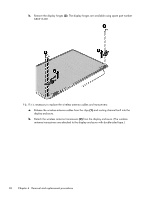
and then swing it up and forward until it rests, Lift the top edge of the display panel
 |
View all HP ENVY m6-1184ca manuals
Add to My Manuals
Save this manual to your list of manuals |
Page 101 highlights
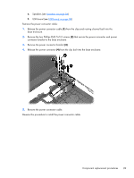
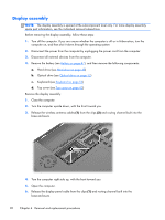
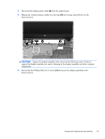
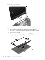
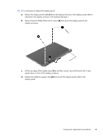
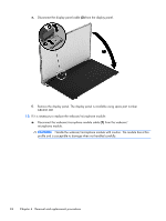
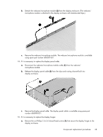
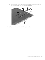
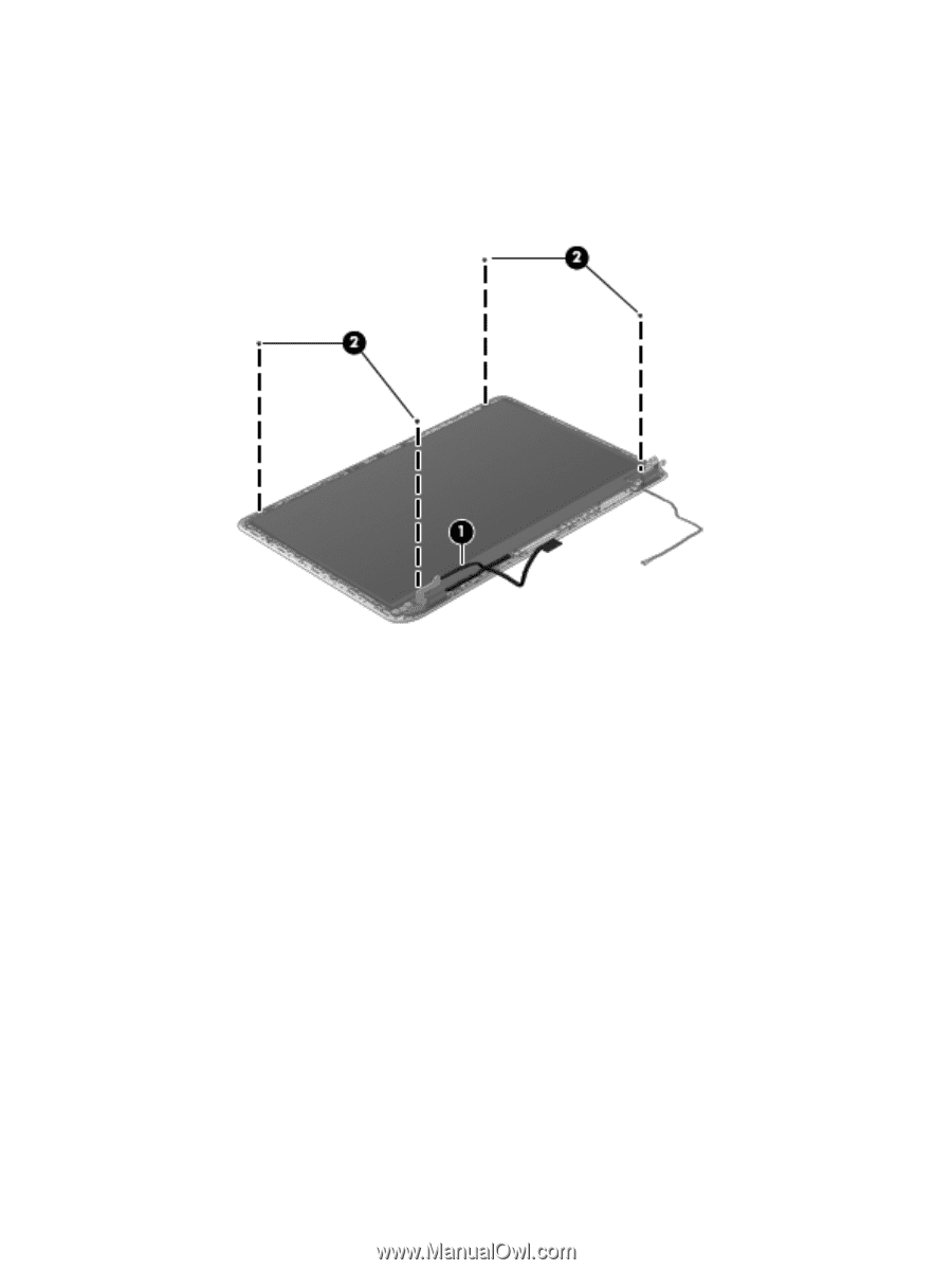
12. If it is necessary to replace the display panel: a. Detach the display panel cable (1) from the display enclosure. (The display panel cable is attached to the display enclosure with double-sided tape.) b. Remove the four Phillips PM2.0×2.0 screws (2) that secure the display panel to the display enclosure. c. Lift the top edge of the display panel (1), and then swing it up and forward until it rests upside down in front of the display enclosure. d. Release the adhesive support strip (2) that secures the display panel cable to the display panel. Component replacement procedures 93
-
 1
1 -
2
-
3
-
4
-
5
-
6
-
7
-
8
-
9
-
10
-
11
-
12
-
13
-
14
-
15
-
16
-
17
-
18
-
19
-
20
-
21
-
22
-
23
-
24
-
25
-
26
-
27
-
28
-
29
-
30
-
31
-
32
-
33
-
34
-
35
-
36
-
37
-
38
-
39
-
40
-
41
-
42
-
43
-
44
-
45
-
46
-
47
-
48
-
49
-
50
-
51
-
52
-
53
-
54
-
55
-
56
-
57
-
58
-
59
-
60
-
61
-
62
-
63
-
64
-
65
-
66
-
67
-
68
-
69
-
70
-
71
-
72
-
73
-
74
-
75
-
76
-
77
-
78
-
79
-
80
-
81
-
82
-
83
-
84
-
85
-
86
-
87
-
88
-
89
-
90
-
91
-
92
-
93
-
94
-
95
-
 96
96 -
 97
97 -
 98
98 -
 99
99 -
 100
100 -
 101
101 -
 102
102 -
 103
103 -
 104
104 -
 105
105 -
 106
106 -
107
-
108
-
109
-
110
-
111
-
112
-
113
-
114
-
115
-
116
-
117
-
118
-
119
-
120
-
121
-
122
-
123
-
124
-
125
 |
 |
12.
If it is necessary to replace the display panel:
a.
Detach the display panel cable
(1)
from the display enclosure. (The display panel cable is
attached to the display enclosure with double-sided tape.)
b.
Remove the four Phillips PM2.0×2.0 screws
(2)
that secure the display panel to the
display enclosure.
c.
Lift the top edge of the display panel
(1)
, and then swing it up and forward until it rests
upside down in front of the display enclosure.
d.
Release the adhesive support strip
(2)
that secures the display panel cable to the
display panel.
Component replacement procedures
93