HP ENVY m6-1184ca HP ENVY m6 Notebook PC Maintenance and Service Guide - Page 87
that secure the heat sink to the system board, and then remove
 |
View all HP ENVY m6-1184ca manuals
Add to My Manuals
Save this manual to your list of manuals |
Page 87 highlights
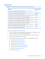
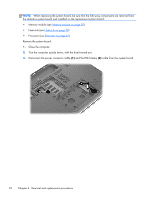
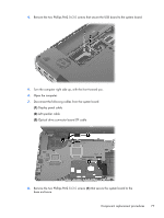
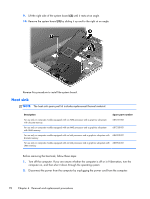
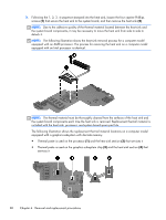
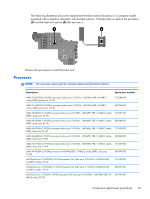
3. Disconnect all external devices from the computer. 4. Remove the battery (see Battery on page 47), and then remove the following components: a. Hard drive (see Hard drive on page 48) b. Optical drive (see Optical drive on page 52) c. Keyboard (see Keyboard on page 56) d. Top cover (see Top cover on page 65) e. Fan (see Fan on page 73) f. System board (see System board on page 75) Remove the heat sink: 1. Turn the system board upside down, with the front toward you. NOTE: Step 2 applies to computer models equipped with a graphics subsystem with discrete memory. See step 3 for heat sink removal information for computer models equipped with a graphics subsystem with UMA memory. 2. Following the 1, 2, 3, 4, 5, 6, 7 sequence stamped into the heat sink, loosen the seven captive Philllips screws (1) and (2) that secure the heat sink to the system board, and then remove the heat sink (3). NOTE: Due to the adhesive quality of the thermal material located between the heat sink and the system board components, it may be necessary to move the heat sink from side to side to detach it. NOTE: The following illustration shows the heat sink removal process for a computer model equipped with an AMD processor. The process for removing the heat sink on a computer model equipped with an Intel processor is identical. Component replacement procedures 79
-
 1
1 -
2
-
3
-
4
-
5
-
6
-
7
-
8
-
9
-
10
-
11
-
12
-
13
-
14
-
15
-
16
-
17
-
18
-
19
-
20
-
21
-
22
-
23
-
24
-
25
-
26
-
27
-
28
-
29
-
30
-
31
-
32
-
33
-
34
-
35
-
36
-
37
-
38
-
39
-
40
-
41
-
42
-
43
-
44
-
45
-
46
-
47
-
48
-
49
-
50
-
51
-
52
-
53
-
54
-
55
-
56
-
57
-
58
-
59
-
60
-
61
-
62
-
63
-
64
-
65
-
66
-
67
-
68
-
69
-
70
-
71
-
72
-
73
-
74
-
75
-
76
-
77
-
78
-
79
-
80
-
81
-
 82
82 -
 83
83 -
 84
84 -
 85
85 -
 86
86 -
 87
87 -
 88
88 -
 89
89 -
 90
90 -
 91
91 -
 92
92 -
93
-
94
-
95
-
96
-
97
-
98
-
99
-
100
-
101
-
102
-
103
-
104
-
105
-
106
-
107
-
108
-
109
-
110
-
111
-
112
-
113
-
114
-
115
-
116
-
117
-
118
-
119
-
120
-
121
-
122
-
123
-
124
-
125
 |
 |