HP ENVY m6-1184ca HP ENVY m6 Notebook PC Maintenance and Service Guide - Page 70
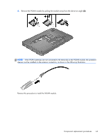
Remove the two Phillips PM2.0×3.0 screws, from the terminals on the WLAN module.
 |
View all HP ENVY m6-1184ca manuals
Add to My Manuals
Save this manual to your list of manuals |
Page 70 highlights
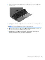
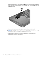
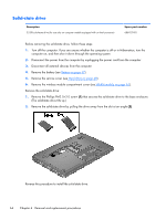
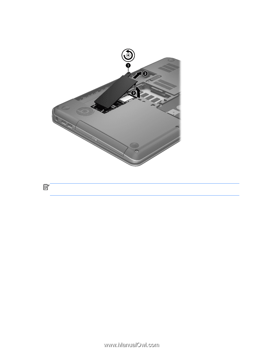
3. Remove the wireless module compartment cover (3) by sliding it away from the computer at an angle. The wireless module compartment cover is available in the Service Cover Kit, spare part number 686920-001. 4. Disconnect the WLAN antenna cables (1) from the terminals on the WLAN module. NOTE: The #1 WLAN antenna cable is connected to the WLAN module #1 terminal. The #2 WLAN antenna cable is connected to the WLAN module #2 terminal. 5. Remove the two Phillips PM2.0×3.0 screws (2) that secure the WLAN module to the base enclosure. (The WLAN module tilts up.) 62 Chapter 4 Removal and replacement procedures
-
 1
1 -
2
-
3
-
4
-
5
-
6
-
7
-
8
-
9
-
10
-
11
-
12
-
13
-
14
-
15
-
16
-
17
-
18
-
19
-
20
-
21
-
22
-
23
-
24
-
25
-
26
-
27
-
28
-
29
-
30
-
31
-
32
-
33
-
34
-
35
-
36
-
37
-
38
-
39
-
40
-
41
-
42
-
43
-
44
-
45
-
46
-
47
-
48
-
49
-
50
-
51
-
52
-
53
-
54
-
55
-
56
-
57
-
58
-
59
-
60
-
61
-
62
-
63
-
64
-
 65
65 -
 66
66 -
 67
67 -
 68
68 -
 69
69 -
 70
70 -
 71
71 -
 72
72 -
 73
73 -
 74
74 -
 75
75 -
76
-
77
-
78
-
79
-
80
-
81
-
82
-
83
-
84
-
85
-
86
-
87
-
88
-
89
-
90
-
91
-
92
-
93
-
94
-
95
-
96
-
97
-
98
-
99
-
100
-
101
-
102
-
103
-
104
-
105
-
106
-
107
-
108
-
109
-
110
-
111
-
112
-
113
-
114
-
115
-
116
-
117
-
118
-
119
-
120
-
121
-
122
-
123
-
124
-
125
 |
 |
3.
Remove the wireless module compartment cover
(3)
by sliding it away from the computer at an
angle. The wireless module compartment cover is available in the Service Cover Kit, spare part
number 686920-001.
4.
Disconnect the WLAN antenna cables
(1)
from the terminals on the WLAN module.
NOTE:
The #1 WLAN antenna cable is connected to the WLAN module #1 terminal. The #2
WLAN antenna cable is connected to the WLAN module #2 terminal.
5.
Remove the two Phillips PM2.0×3.0 screws
(2)
that secure the WLAN module to the
base enclosure. (The WLAN module tilts up.)
62
Chapter 4
Removal and replacement procedures