HP ENVY m6-1184ca HP ENVY m6 Notebook PC Maintenance and Service Guide - Page 97
Remove the power connector bracket, connector bracket to the base enclosure.
 |
View all HP ENVY m6-1184ca manuals
Add to My Manuals
Save this manual to your list of manuals |
Page 97 highlights
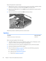
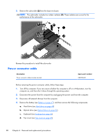
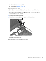
e. Speakers (see Speakers on page 84) f. USB board (see USB board on page 86) Remove the power connector cable: 1. Release the power connector cable (1) from the clips and routing channel built into the base enclosure. 2. Remove the two Phillips PM2.5×5.0 screws (2) that secure the power connector and power connector bracket to the base enclosure. 3. Remove the power connector bracket (3). 4. Release the power connector (4) from the clip built into the base enclosure. 5. Remove the power connector cable. Reverse this procedure to install the power connector cable. Component replacement procedures 89
-
 1
1 -
2
-
3
-
4
-
5
-
6
-
7
-
8
-
9
-
10
-
11
-
12
-
13
-
14
-
15
-
16
-
17
-
18
-
19
-
20
-
21
-
22
-
23
-
24
-
25
-
26
-
27
-
28
-
29
-
30
-
31
-
32
-
33
-
34
-
35
-
36
-
37
-
38
-
39
-
40
-
41
-
42
-
43
-
44
-
45
-
46
-
47
-
48
-
49
-
50
-
51
-
52
-
53
-
54
-
55
-
56
-
57
-
58
-
59
-
60
-
61
-
62
-
63
-
64
-
65
-
66
-
67
-
68
-
69
-
70
-
71
-
72
-
73
-
74
-
75
-
76
-
77
-
78
-
79
-
80
-
81
-
82
-
83
-
84
-
85
-
86
-
87
-
88
-
89
-
90
-
91
-
 92
92 -
 93
93 -
 94
94 -
 95
95 -
 96
96 -
 97
97 -
 98
98 -
 99
99 -
 100
100 -
 101
101 -
 102
102 -
103
-
104
-
105
-
106
-
107
-
108
-
109
-
110
-
111
-
112
-
113
-
114
-
115
-
116
-
117
-
118
-
119
-
120
-
121
-
122
-
123
-
124
-
125
 |
 |

e.
Speakers (see
Speakers
on page
84
)
f.
USB board (see
USB board
on page
86
)
Remove the power connector cable:
1.
Release the power connector cable
(1)
from the clips and routing channel built into the
base enclosure.
2.
Remove the two Phillips PM2.5×5.0 screws
(2)
that secure the power connector and power
connector bracket to the base enclosure.
3.
Remove the power connector bracket
(3)
.
4.
Release the power connector
(4)
from the clip built into the base enclosure.
5.
Remove the power connector cable.
Reverse this procedure to install the power connector cable.
Component replacement procedures
89