HP ENVY m6-n113dx HP ENVY m6 Notebook PC HP ENVY Notebook PC Maintenance and S - Page 79
Remove the connector board, by sliding it up and to the right at an angle.
 |
View all HP ENVY m6-n113dx manuals
Add to My Manuals
Save this manual to your list of manuals |
Page 79 highlights
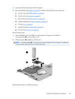
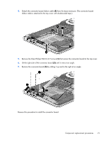
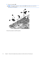
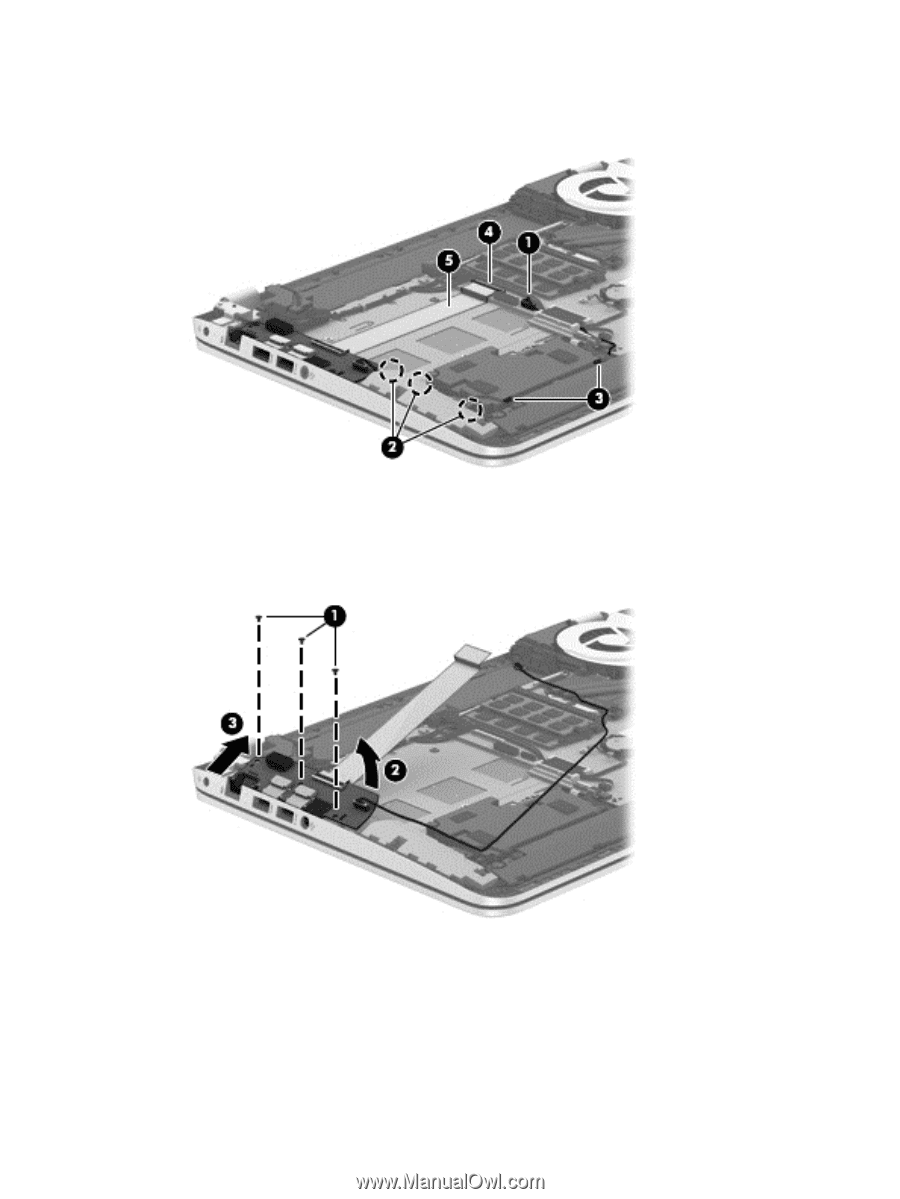
4. Detach the connector board ribbon cable (5) from the base enclosure. (The connector board ribbon cable is attached to the top cover with double-sided tape.) 5. Remove the three Phillips PM2.0×2.9 screws (1) that secure the connector board to the top cover. 6. Lift the right side of the connector board (2) until it rests at an angle. 7. Remove the connector board (3) by sliding it up and to the right at an angle. Reverse this procedure to install the connector board. Component replacement procedures 71
-
 1
1 -
2
-
3
-
4
-
5
-
6
-
7
-
8
-
9
-
10
-
11
-
12
-
13
-
14
-
15
-
16
-
17
-
18
-
19
-
20
-
21
-
22
-
23
-
24
-
25
-
26
-
27
-
28
-
29
-
30
-
31
-
32
-
33
-
34
-
35
-
36
-
37
-
38
-
39
-
40
-
41
-
42
-
43
-
44
-
45
-
46
-
47
-
48
-
49
-
50
-
51
-
52
-
53
-
54
-
55
-
56
-
57
-
58
-
59
-
60
-
61
-
62
-
63
-
64
-
65
-
66
-
67
-
68
-
69
-
70
-
71
-
72
-
73
-
 74
74 -
 75
75 -
 76
76 -
 77
77 -
 78
78 -
 79
79 -
 80
80 -
 81
81 -
 82
82 -
 83
83 -
 84
84 -
85
-
86
-
87
-
88
-
89
-
90
-
91
-
92
-
93
-
94
-
95
-
96
-
97
-
98
-
99
-
100
-
101
-
102
-
103
-
104
-
105
-
106
 |
 |
4.
Detach the connector board ribbon cable
(5)
from the base enclosure. (The connector board
ribbon cable is attached to the top cover with double-sided tape.)
5.
Remove the three Phillips PM2.0×2.9 screws
(1)
that secure the connector board to the top cover.
6.
Lift the right side of the connector board
(2)
until it rests at an angle.
7.
Remove the connector board
(3)
by sliding it up and to the right at an angle.
Reverse this procedure to install the connector board.
Component replacement procedures
71