HP G72-b66US HP G72 Notebook PC - Maintenance and Service Guide - Page 50
Component replacement procedures, Serial number - specifications
 |
View all HP G72-b66US manuals
Add to My Manuals
Save this manual to your list of manuals |
Page 50 highlights
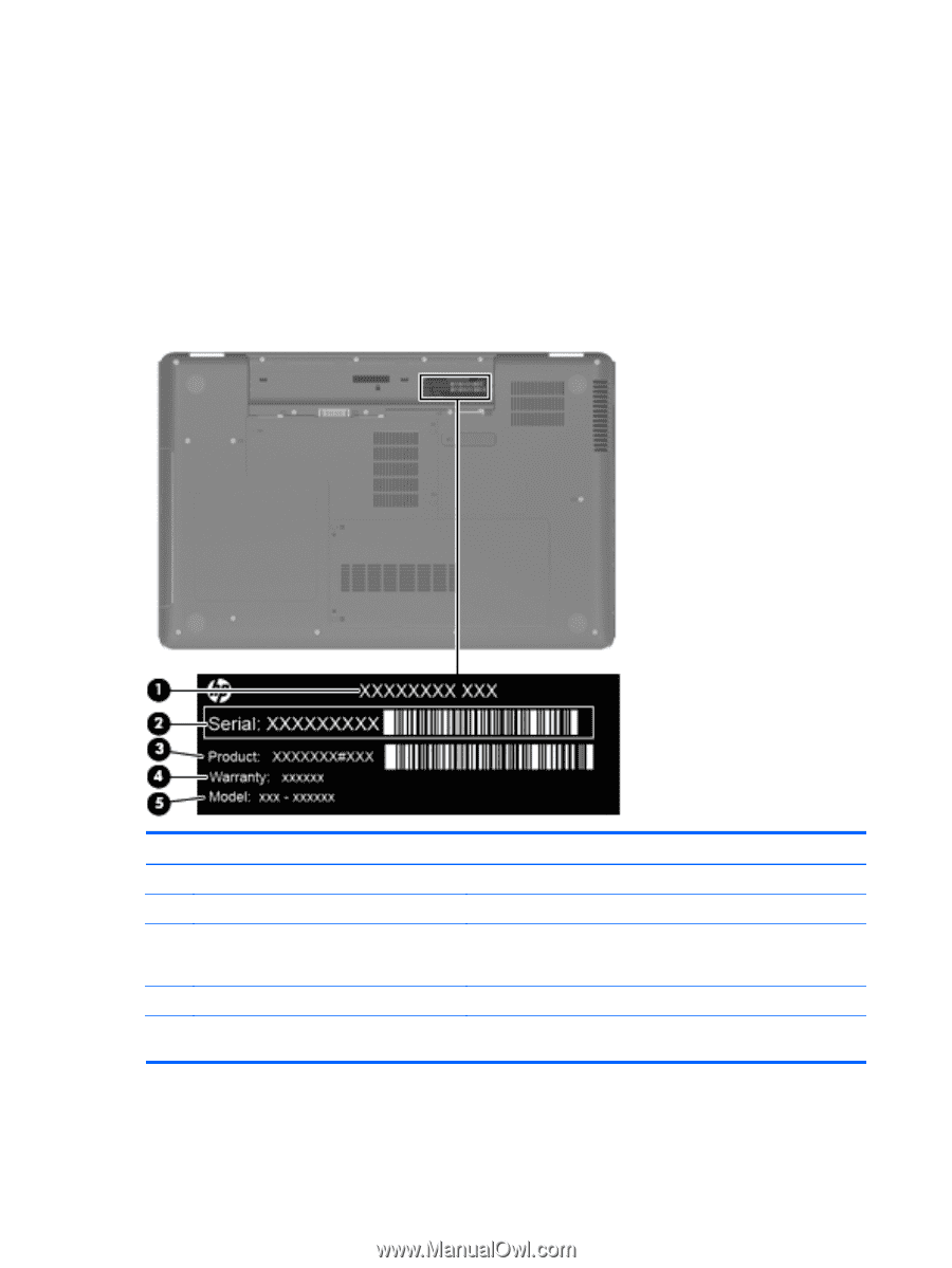
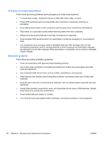
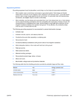
Component replacement procedures This chapter provides removal and replacement procedures. There are as many as 75 screws, in 12 different sizes, that must be removed, replaced, or loosened when servicing the computer. Make special note of each screw size and location during removal and replacement. Serial number The serial number label, located in the battery bay of the computer, provides important information that you may need when contacting technical support. Component (1) Product name (2) Serial number (s/n) (3) Part number/Product number (p/n) (4) Warranty period (5) Model description Description The name affixed to the front of the computer. An alphanumeric identifier that is unique to each product. This number provides specific information about the product's hardware components. The part number helps a service technician to determine what components and parts are needed. The duration of the warranty period for the computer. An alphanumeric identifier used to locate documents, drivers, and support for the computer. 40 Chapter 4 Removal and replacement procedures ENWW
-
 1
1 -
2
-
3
-
4
-
5
-
6
-
7
-
8
-
9
-
10
-
11
-
12
-
13
-
14
-
15
-
16
-
17
-
18
-
19
-
20
-
21
-
22
-
23
-
24
-
25
-
26
-
27
-
28
-
29
-
30
-
31
-
32
-
33
-
34
-
35
-
36
-
37
-
38
-
39
-
40
-
41
-
42
-
43
-
44
-
 45
45 -
 46
46 -
 47
47 -
 48
48 -
 49
49 -
 50
50 -
 51
51 -
 52
52 -
 53
53 -
 54
54 -
 55
55 -
56
-
57
-
58
-
59
-
60
-
61
-
62
-
63
-
64
-
65
-
66
-
67
-
68
-
69
-
70
-
71
-
72
-
73
-
74
-
75
-
76
-
77
-
78
-
79
-
80
-
81
-
82
-
83
-
84
-
85
-
86
-
87
-
88
-
89
-
90
-
91
-
92
-
93
-
94
-
95
-
96
-
97
-
98
-
99
-
100
-
101
-
102
-
103
-
104
-
105
-
106
-
107
-
108
-
109
-
110
-
111
-
112
-
113
-
114
-
115
-
116
-
117
-
118
-
119
-
120
-
121
-
122
-
123
-
124
-
125
-
126
-
127
-
128
-
129
-
130
-
131
-
132
-
133
-
134
-
135
-
136
-
137
-
138
-
139
-
140
 |
 |