HP G72-b66US HP G72 Notebook PC - Maintenance and Service Guide - Page 79
Display assembly, Remove the display assembly
 |
View all HP G72-b66US manuals
Add to My Manuals
Save this manual to your list of manuals |
Page 79 highlights
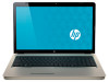
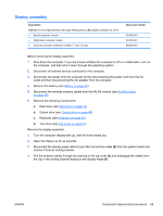
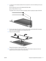
Display assembly Description 39.6-cm (15.6-in) High Definition (HD), light-emitting diode (LED) display assembly for use in: ● Biscotti computer models ● Matte black computer models ● Charcoal computer models (for models 1.1 and 1.2 only) Spare part number 612094-001 612095-001 620538-001 Before removing the display assembly: 1. Shut down the computer. If you are unsure whether the computer is off or in Hibernation, turn on the computer, and then shut it down through the operating system. 2. Disconnect all external devices connected to the computer. 3. Disconnect the power from the computer by first disconnecting the power cord from the AC outlet and then disconnecting the AC adapter from the computer. 4. Remove the battery (see Battery on page 42). 5. Disconnect the wireless antenna cables from the WLAN module (see WLAN module on page 48). 6. Remove the following components: a. Hard drive (see Hard drive on page 43) b. Optical drive (see Optical drive on page 46) c. Keyboard (see Keyboard on page 54) d. Top cover (see Top cover on page 57) Remove the display assembly: 1. Turn the computer display-side up, with the front toward you. 2. Open the display as far as possible. 3. Disconnect the display panel cable (1) and the microphone cable (2) from the system board and remove it from its routing channel. 4. Pull the antenna cables through the opening in the top cover (3) and disengage the cables from the clip in the routing channel leading to the display hinge (4). ENWW Component replacement procedures 69
-
 1
1 -
2
-
3
-
4
-
5
-
6
-
7
-
8
-
9
-
10
-
11
-
12
-
13
-
14
-
15
-
16
-
17
-
18
-
19
-
20
-
21
-
22
-
23
-
24
-
25
-
26
-
27
-
28
-
29
-
30
-
31
-
32
-
33
-
34
-
35
-
36
-
37
-
38
-
39
-
40
-
41
-
42
-
43
-
44
-
45
-
46
-
47
-
48
-
49
-
50
-
51
-
52
-
53
-
54
-
55
-
56
-
57
-
58
-
59
-
60
-
61
-
62
-
63
-
64
-
65
-
66
-
67
-
68
-
69
-
70
-
71
-
72
-
73
-
 74
74 -
 75
75 -
 76
76 -
 77
77 -
 78
78 -
 79
79 -
 80
80 -
 81
81 -
 82
82 -
 83
83 -
 84
84 -
85
-
86
-
87
-
88
-
89
-
90
-
91
-
92
-
93
-
94
-
95
-
96
-
97
-
98
-
99
-
100
-
101
-
102
-
103
-
104
-
105
-
106
-
107
-
108
-
109
-
110
-
111
-
112
-
113
-
114
-
115
-
116
-
117
-
118
-
119
-
120
-
121
-
122
-
123
-
124
-
125
-
126
-
127
-
128
-
129
-
130
-
131
-
132
-
133
-
134
-
135
-
136
-
137
-
138
-
139
-
140
 |
 |