HP G72-b66US HP G72 Notebook PC - Maintenance and Service Guide - Page 85
System board, Remove the battery see - graphics card
 |
View all HP G72-b66US manuals
Add to My Manuals
Save this manual to your list of manuals |
Page 85 highlights
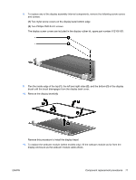
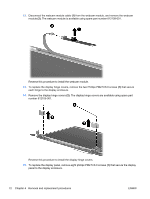
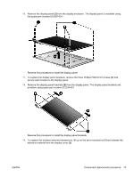
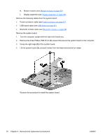
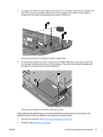
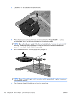
System board NOTE: The system board spare part kit includes UMA or discrete graphics subsystem memory and replacement thermal material. Description HD 5430/1 G discrete system board with card reader 1.1 (for model 1.1 only) HD 5430/512 MB discrete system board with card reader 1.1 (for model 1.1 only) HD 5430/512 MB discrete system board with card reader (for model 1.0 only) HD 5430/1 G discrete system board with card reader (for model 1.0 only) HD UMA system board with card reader (for model 1.2 only) HD 1G discrete system board with card reader (for model 1.2 only) HD 512 MB discrete system board with card reader (for model 1.2 only) HD UMA system board with card reader (for model 1.2 only) Spare part number 615847-001 615848-001 629120-001 629121-001 629122-001 630948-001 630949-001 630950-001 When replacing the system board, be sure that the following components are removed from the defective system board and installed on the replacement system board: ● RTC battery (see RTC battery on page 52) ● Memory modules (see Memory module on page 51) ● WLAN module (see WLAN module on page 48) ● Modem module (see Modem module on page 63) Before removing the system board: 1. Shut down the computer. If you are unsure whether the computer is off or in Hibernation, turn on the computer, and then shut it down through the operating system. 2. Disconnect all external devices connected to the computer. 3. Disconnect the power from the computer by first disconnecting the power cord from the AC outlet and then disconnecting the AC adapter from the computer. 4. Remove the battery (see Battery on page 42). 5. Remove the following components: a. Hard drive (see Hard drive on page 43) b. Optical drive (see Optical drive on page 46) c. WLAN module (see WLAN module on page 48) d. Memory module (see Memory module on page 51) e. RTC battery (see RTC battery on page 52) f. Keyboard (see Keyboard on page 54) g. Top cover (see Top cover on page 57) ENWW Component replacement procedures 75
-
 1
1 -
2
-
3
-
4
-
5
-
6
-
7
-
8
-
9
-
10
-
11
-
12
-
13
-
14
-
15
-
16
-
17
-
18
-
19
-
20
-
21
-
22
-
23
-
24
-
25
-
26
-
27
-
28
-
29
-
30
-
31
-
32
-
33
-
34
-
35
-
36
-
37
-
38
-
39
-
40
-
41
-
42
-
43
-
44
-
45
-
46
-
47
-
48
-
49
-
50
-
51
-
52
-
53
-
54
-
55
-
56
-
57
-
58
-
59
-
60
-
61
-
62
-
63
-
64
-
65
-
66
-
67
-
68
-
69
-
70
-
71
-
72
-
73
-
74
-
75
-
76
-
77
-
78
-
79
-
 80
80 -
 81
81 -
 82
82 -
 83
83 -
 84
84 -
 85
85 -
 86
86 -
 87
87 -
 88
88 -
 89
89 -
 90
90 -
91
-
92
-
93
-
94
-
95
-
96
-
97
-
98
-
99
-
100
-
101
-
102
-
103
-
104
-
105
-
106
-
107
-
108
-
109
-
110
-
111
-
112
-
113
-
114
-
115
-
116
-
117
-
118
-
119
-
120
-
121
-
122
-
123
-
124
-
125
-
126
-
127
-
128
-
129
-
130
-
131
-
132
-
133
-
134
-
135
-
136
-
137
-
138
-
139
-
140
 |
 |
