HP G72-b66US HP G72 Notebook PC - Maintenance and Service Guide - Page 86
Remove the three Phillips PM2.5×4.0, Grasp the right edge
 |
View all HP G72-b66US manuals
Add to My Manuals
Save this manual to your list of manuals |
Page 86 highlights
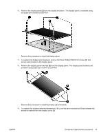
h. Modem module (see Modem module on page 63) i. Display assembly (see Display assembly on page 69) Remove the following cables from the system board: ● Power connector cable (see Power connector on page 67) ● USB board cable (see USB board on page 65) ● Bluetooth module cable (see Bluetooth module on page 68) Remove the system board: 1. Turn the computer upright with the right side toward you. 2. Remove the three Phillips PM2.5×4.0 (1) screws that secure the system board to the computer. 3. Grasp the right edge (2) of the system board. 4. Lift the system board (3), and pull it away from the base enclosure at an angle. Reverse this procedure to install the system board. 76 Chapter 4 Removal and replacement procedures ENWW
-
 1
1 -
2
-
3
-
4
-
5
-
6
-
7
-
8
-
9
-
10
-
11
-
12
-
13
-
14
-
15
-
16
-
17
-
18
-
19
-
20
-
21
-
22
-
23
-
24
-
25
-
26
-
27
-
28
-
29
-
30
-
31
-
32
-
33
-
34
-
35
-
36
-
37
-
38
-
39
-
40
-
41
-
42
-
43
-
44
-
45
-
46
-
47
-
48
-
49
-
50
-
51
-
52
-
53
-
54
-
55
-
56
-
57
-
58
-
59
-
60
-
61
-
62
-
63
-
64
-
65
-
66
-
67
-
68
-
69
-
70
-
71
-
72
-
73
-
74
-
75
-
76
-
77
-
78
-
79
-
80
-
 81
81 -
 82
82 -
 83
83 -
 84
84 -
 85
85 -
 86
86 -
 87
87 -
 88
88 -
 89
89 -
 90
90 -
 91
91 -
92
-
93
-
94
-
95
-
96
-
97
-
98
-
99
-
100
-
101
-
102
-
103
-
104
-
105
-
106
-
107
-
108
-
109
-
110
-
111
-
112
-
113
-
114
-
115
-
116
-
117
-
118
-
119
-
120
-
121
-
122
-
123
-
124
-
125
-
126
-
127
-
128
-
129
-
130
-
131
-
132
-
133
-
134
-
135
-
136
-
137
-
138
-
139
-
140
 |
 |
h.
Modem module (see
Modem module
on page
63
)
i.
Display assembly (see
Display assembly
on page
69
)
Remove the following cables from the system board:
●
Power connector cable (see
Power connector
on page
67
)
●
USB board cable (see
USB board
on page
65
)
●
Bluetooth module cable (see
Bluetooth module
on page
68
)
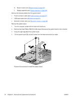
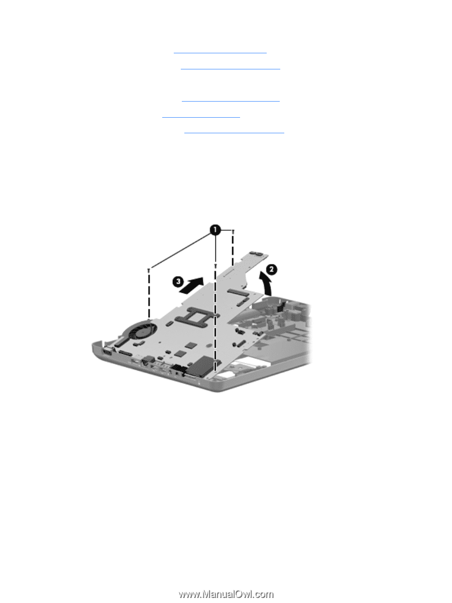
Remove the system board:
1.
Turn the computer upright with the right side toward you.
2.
Remove the three Phillips PM2.5×4.0
(1)
screws that secure the system board to the computer.
3.
Grasp the right edge
(2)
of the system board.
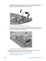
4.
Lift the system board
(3)
, and pull it away from the base enclosure at an angle.
Reverse this procedure to install the system board.
76
Chapter 4
Removal and replacement procedures
ENWW