HP Integrity cx2600 HP Integrity cx2600 Operations and Maintenance Guide - Page 137
Installing the LED Status Panel, Removing the LED Status Panel, CAUTION
 |
View all HP Integrity cx2600 manuals
Add to My Manuals
Save this manual to your list of manuals |
Page 137 highlights
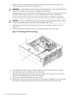
5. Remove the two noncaptive screws that secure the LED status panel board to the threaded standoffs on the deck, and slide the board forward to disengage the board lock apertures from the keyed standoffs (two each). 6. Remove the board by lifting it off of the deck assembly. Figure 7-18 Removing the LED Status Panel LED Board Mounting Screws chasdvdxtnd CD/DVD LED Board Installing the LED Status Panel CAUTION: Observe all ESD safety precautions while performing this procedure. Failure to follow ESD safety precautions can result in damage to the server. To install an LED status panel, follow these steps: 1. Engage the board lock apertures on the keyed standoffs on the deck, and slide the board toward the rear to lock it. Install the two screws securing the board to the threaded standoffs. 2. Connect the cable to the small connector of the LED status panel. 3. Position the CD/DVD deck and LED status panel assembly into the front of the chassis and fasten the two screws that secure it to the chassis (Figure 7-17). Removing and Replacing the LED Status Panel 137
-
 1
1 -
2
-
3
-
4
-
5
-
6
-
7
-
8
-
9
-
10
-
11
-
12
-
13
-
14
-
15
-
16
-
17
-
18
-
19
-
20
-
21
-
22
-
23
-
24
-
25
-
26
-
27
-
28
-
29
-
30
-
31
-
32
-
33
-
34
-
35
-
36
-
37
-
38
-
39
-
40
-
41
-
42
-
43
-
44
-
45
-
46
-
47
-
48
-
49
-
50
-
51
-
52
-
53
-
54
-
55
-
56
-
57
-
58
-
59
-
60
-
61
-
62
-
63
-
64
-
65
-
66
-
67
-
68
-
69
-
70
-
71
-
72
-
73
-
74
-
75
-
76
-
77
-
78
-
79
-
80
-
81
-
82
-
83
-
84
-
85
-
86
-
87
-
88
-
89
-
90
-
91
-
92
-
93
-
94
-
95
-
96
-
97
-
98
-
99
-
100
-
101
-
102
-
103
-
104
-
105
-
106
-
107
-
108
-
109
-
110
-
111
-
112
-
113
-
114
-
115
-
116
-
117
-
118
-
119
-
120
-
121
-
122
-
123
-
124
-
125
-
126
-
127
-
128
-
129
-
130
-
131
-
 132
132 -
 133
133 -
 134
134 -
 135
135 -
 136
136 -
 137
137 -
 138
138 -
 139
139 -
 140
140 -
 141
141 -
 142
142 -
143
-
144
-
145
-
146
-
147
-
148
-
149
-
150
-
151
-
152
-
153
-
154
-
155
-
156
-
157
-
158
-
159
-
160
-
161
-
162
-
163
-
164
-
165
-
166
-
167
-
168
 |
 |
