HP Integrity cx2600 HP Integrity cx2600 Operations and Maintenance Guide - Page 47
Securing Heatsink Captive Screws, Sliding the Processor Power Module
 |
View all HP Integrity cx2600 manuals
Add to My Manuals
Save this manual to your list of manuals |
Page 47 highlights
Figure 3-24 Securing Heatsink Captive Screws 14. Connect the power cable for the processor turbo fan to its connector on the system board. 15. Slide the CPU power module on the system board metal mounting bracket so that the power module connector aligns with the connector on the processor. Figure 3-25 Sliding the Processor Power Module Installing Processors 47
-
 1
1 -
2
-
3
-
4
-
5
-
6
-
7
-
8
-
9
-
10
-
11
-
12
-
13
-
14
-
15
-
16
-
17
-
18
-
19
-
20
-
21
-
22
-
23
-
24
-
25
-
26
-
27
-
28
-
29
-
30
-
31
-
32
-
33
-
34
-
35
-
36
-
37
-
38
-
39
-
40
-
41
-
 42
42 -
 43
43 -
 44
44 -
 45
45 -
 46
46 -
 47
47 -
 48
48 -
 49
49 -
 50
50 -
 51
51 -
 52
52 -
53
-
54
-
55
-
56
-
57
-
58
-
59
-
60
-
61
-
62
-
63
-
64
-
65
-
66
-
67
-
68
-
69
-
70
-
71
-
72
-
73
-
74
-
75
-
76
-
77
-
78
-
79
-
80
-
81
-
82
-
83
-
84
-
85
-
86
-
87
-
88
-
89
-
90
-
91
-
92
-
93
-
94
-
95
-
96
-
97
-
98
-
99
-
100
-
101
-
102
-
103
-
104
-
105
-
106
-
107
-
108
-
109
-
110
-
111
-
112
-
113
-
114
-
115
-
116
-
117
-
118
-
119
-
120
-
121
-
122
-
123
-
124
-
125
-
126
-
127
-
128
-
129
-
130
-
131
-
132
-
133
-
134
-
135
-
136
-
137
-
138
-
139
-
140
-
141
-
142
-
143
-
144
-
145
-
146
-
147
-
148
-
149
-
150
-
151
-
152
-
153
-
154
-
155
-
156
-
157
-
158
-
159
-
160
-
161
-
162
-
163
-
164
-
165
-
166
-
167
-
168
 |
 |

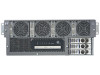
Figure 3-24 Securing Heatsink Captive Screws
14.
Connect the power cable for the processor turbo fan to its connector on the system board.
15.
Slide the CPU power module on the system board metal mounting bracket so that the power
module connector aligns with the connector on the processor.
Figure 3-25 Sliding the Processor Power Module
Installing Processors
47