HP Integrity rx6600 Rack to Pedestal Conversion Guide - HP Integrity rx6600 Se - Page 13
Floor Installation Procedure, Ramp Attachment Detail, CAUTION, WARNING
 |
View all HP Integrity rx6600 manuals
Add to My Manuals
Save this manual to your list of manuals |
Page 13 highlights
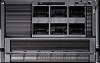
Figure 2-6 Ramp Attachment Detail CAUTION: Screws which are not fully inserted may hook the caster wheels or the bottom of the server. 13. Roll the server off the pallet. See Figure 2-5. Floor Installation Procedure Follow these steps to attach the caster wheels when the sever is on the floor. 1. Turn the server onto its right side. WARNING! Be careful when lifting the server as it is heavy. CAUTION: Be sure the server handles are in (against the server) to prevent damaging the handles. 2. With the left side facing up, locate the attachment points for the left caster wheels by finding the rivets that are the same distance part as the holes in the caster wheel assembly. 3. Align the holes in the caster wheel assembly below the rivets on the server. Figure 2-7 shows the left side caster wheels in place. 4. Slide each caster wheel assembly up until it locks into places. Turn the server over onto the left side and repeat the process for the right side wheels. After all four wheels are attached the server can rest in its normal horizontal position, on the wheels, for the remainder of the pedestal kit installation. Installing the Caster Wheels 13
-
 1
1 -
2
-
3
-
4
-
5
-
6
-
7
-
 8
8 -
 9
9 -
 10
10 -
 11
11 -
 12
12 -
 13
13 -
 14
14 -
 15
15 -
 16
16 -
 17
17 -
 18
18 -
19
-
20
-
21
 |
 |
