HP Mini 1104 HP Mini 1104 - Maintenance and Service Guide - Page 41
Remove the Phillips PM2.0×3.0 screw
 |
View all HP Mini 1104 manuals
Add to My Manuals
Save this manual to your list of manuals |
Page 41 highlights
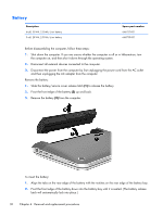
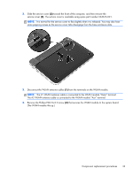
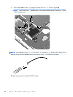
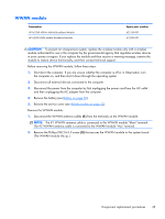
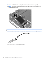
2. Slide the service cover (2) toward the front of the computer, and then remove the service cover (3). The service cover is available using spare part number 663676-001. NOTE: It is normal for the service cover to flex slightly when it is released. You may also hear some popping noises as the service cover tabs disengage from the base enclosure slots. 3. Disconnect the WLAN antenna cables (1) from the terminals on the WLAN module. NOTE: The #1 WLAN antenna cable is connected to the WLAN module "Main" terminal. The #2 WLAN antenna cable is connected to the WLAN module "Aux" terminal. 4. Remove the Phillips PM2.0×3.0 screw (2) that secures the WLAN module to the system board. (The WLAN module tilts up.) Component replacement procedures 33
-
 1
1 -
2
-
3
-
4
-
5
-
6
-
7
-
8
-
9
-
10
-
11
-
12
-
13
-
14
-
15
-
16
-
17
-
18
-
19
-
20
-
21
-
22
-
23
-
24
-
25
-
26
-
27
-
28
-
29
-
30
-
31
-
32
-
33
-
34
-
35
-
 36
36 -
 37
37 -
 38
38 -
 39
39 -
 40
40 -
 41
41 -
 42
42 -
 43
43 -
 44
44 -
 45
45 -
 46
46 -
47
-
48
-
49
-
50
-
51
-
52
-
53
-
54
-
55
-
56
-
57
-
58
-
59
-
60
-
61
-
62
-
63
-
64
-
65
-
66
-
67
-
68
-
69
-
70
-
71
-
72
-
73
-
74
-
75
-
76
-
77
-
78
-
79
-
80
-
81
-
82
-
83
-
84
-
85
-
86
-
87
-
88
-
89
-
90
-
91
 |
 |

2.
Slide the service cover
(2)
toward the front of the computer, and then remove the
service cover
(3)
. The service cover is available using spare part number 663676-001.
NOTE:
It is normal for the service cover to flex slightly when it is released. You may also hear
some popping noises as the service cover tabs disengage from the base enclosure slots.
3.
Disconnect the WLAN antenna cables
(1)
from the terminals on the WLAN module.
NOTE:
The #1 WLAN antenna cable is connected to the WLAN module “Main” terminal.
The #2 WLAN antenna cable is connected to the WLAN module “Aux” terminal.
4.
Remove the Phillips PM2.0×3.0 screw
(2)
that secures the WLAN module to the system board.
(The WLAN module tilts up.)
Component replacement procedures
33