HP Mini 210-2000 HP Mini 210 - Maintenance and Service Guide - Page 63
Display assembly
 |
View all HP Mini 210-2000 manuals
Add to My Manuals
Save this manual to your list of manuals |
Page 63 highlights
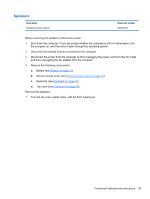
Display assembly Description Spare part number 25.7-cm (10.1-in) display assembly (includes display panel cable, 2 WLAN transceivers and cables, 2 WWAN transceivers and cables (select models only), and webcam/microphone module and cable): ● HD, flush glass display assembly in charcoal 622339-001 ● HD, flush glass display assembly in crimson red 622340-001 ● HD, flush glass display assembly in luminous rose 622341-001 ● HD, flush glass display assembly in ocean drive blue 622342-001 ● HD, flush glass display assembly in lavender frost 622343-001 ● WSVGA, flush glass display assembly in charcoal 622334-001 ● WSVGA, flush glass display assembly in crimson red 622335-001 ● WSVGA, flush glass display assembly in luminous rose 622336-001 ● WSVGA, flush glass display assembly in ocean drive blue 622337-001 ● WSVGA, flush glass display assembly in lavender frost 622338-001 Before removing the display assembly, follow these steps: 1. Shut down the computer. If you are unsure whether the computer is off or in Hibernation, turn the computer on, and then shut it down through the operating system. 2. Disconnect all external devices connected to the computer. 3. Disconnect the power from the computer by first unplugging the power cord from the AC outlet and then unplugging the AC adapter from the computer. 4. Remove the following components: a. Battery (see Battery on page 31). b. Service access cover (see Service access cover on page 34). c. Keyboard (see Keyboard on page 46). d. Top cover (see Top cover on page 49). 5. Disconnect the WWAN antenna cables from the WWAN module (see WWAN and GPS modules (select models only) on page 40). 6. Disconnect the WLAN antenna cables from the WLAN module (see WLAN module on page 42). Remove the display assembly: 1. Close the computer. 2. Turn the computer upside down, with the front toward you. Component replacement procedures 55
-
 1
1 -
2
-
3
-
4
-
5
-
6
-
7
-
8
-
9
-
10
-
11
-
12
-
13
-
14
-
15
-
16
-
17
-
18
-
19
-
20
-
21
-
22
-
23
-
24
-
25
-
26
-
27
-
28
-
29
-
30
-
31
-
32
-
33
-
34
-
35
-
36
-
37
-
38
-
39
-
40
-
41
-
42
-
43
-
44
-
45
-
46
-
47
-
48
-
49
-
50
-
51
-
52
-
53
-
54
-
55
-
56
-
57
-
 58
58 -
 59
59 -
 60
60 -
 61
61 -
 62
62 -
 63
63 -
 64
64 -
 65
65 -
 66
66 -
 67
67 -
 68
68 -
69
-
70
-
71
-
72
-
73
-
74
-
75
-
76
-
77
-
78
-
79
-
80
-
81
-
82
-
83
-
84
-
85
-
86
-
87
-
88
-
89
-
90
-
91
-
92
-
93
-
94
-
95
-
96
-
97
-
98
-
99
-
100
-
101
-
102
-
103
-
104
 |
 |