HP Mini 210-2000 HP Mini 210 - Maintenance and Service Guide - Page 70
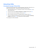
Remove the 2 Phillips 2.0×4.0 screws, Disconnect the power connector cable from the system board.
 |
View all HP Mini 210-2000 manuals
Add to My Manuals
Save this manual to your list of manuals |
Page 70 highlights
5. Disconnect the WWAN antenna cables from the WWAN module (see WWAN and GPS modules (select models only) on page 40). 6. Disconnect the WLAN antenna cables from the WLAN module (see WLAN module on page 42). When replacing the system board, be sure that the following components are removed from the defective system board and installed on the replacement system board: ● SIM (see SIM on page 33) ● WWAN module (see WWAN and GPS modules (select models only) on page 40) ● WLAN module (see WLAN module on page 42) ● Memory module (see Memory module on page 44) ● RTC battery (see RTC battery on page 45) ● Fan/heat sink assembly (see Fan/heat sink assembly on page 59) Remove the system board: 1. Disconnect the power connector cable from the system board. 2. Remove the 2 Phillips 2.0×4.0 screws (1) that secure the system board to the base enclosure. 3. Lift the right side of the system board (2) until it rests at an angle. 62 Chapter 4 Removal and replacement procedures
-
 1
1 -
2
-
3
-
4
-
5
-
6
-
7
-
8
-
9
-
10
-
11
-
12
-
13
-
14
-
15
-
16
-
17
-
18
-
19
-
20
-
21
-
22
-
23
-
24
-
25
-
26
-
27
-
28
-
29
-
30
-
31
-
32
-
33
-
34
-
35
-
36
-
37
-
38
-
39
-
40
-
41
-
42
-
43
-
44
-
45
-
46
-
47
-
48
-
49
-
50
-
51
-
52
-
53
-
54
-
55
-
56
-
57
-
58
-
59
-
60
-
61
-
62
-
63
-
64
-
 65
65 -
 66
66 -
 67
67 -
 68
68 -
 69
69 -
 70
70 -
 71
71 -
 72
72 -
 73
73 -
 74
74 -
 75
75 -
76
-
77
-
78
-
79
-
80
-
81
-
82
-
83
-
84
-
85
-
86
-
87
-
88
-
89
-
90
-
91
-
92
-
93
-
94
-
95
-
96
-
97
-
98
-
99
-
100
-
101
-
102
-
103
-
104
 |
 |
